2011-3-25 12:26:32
views
In aluminum electrolytic capacitors, the layer of insulating aluminum oxide on the surface of the aluminum plate acts as the dielectric, and it is the thinness of this layer that allows for a relatively high capacitance in a small volume. This oxide has a dielectric constant of 10, which is several times higher than most common polymer insulators. This layer can withstand an electric field strength of the order of 25 megavolts per meter which is significant fraction of that of common polymers. This combination of high capacitance and reasonably high voltage result in high energy density.
2011-3-24 12:20:30
views
The features of film capacitor are non-inductive construction, self-healing, high reliable and superior performance in high frequency applications. It is applied to filter and noise suppression circuit, pulse logic and timing circuit, DC blocking, by-passing and signal coupling in general communication equipment. The construction of film capacitor includes polyester film dielectric with vacuum-evaporated metal electrodes, radial leads of tinned wire are electrically welded to the contact metal layer on the ends of capacitor winding, epoxy resin coating.
Are you interested in learning more details about Film Capacitors? jb Capacitors manufactures and markets Plastic Film Capacitors, Including Mylar Polyester Film Capacitor, Metallized Polyester Film Capacitor, Box Type Met Polyester Film Capacitor, X2 Metallized Polypropylene Film Capacitor and Metallized Polypropylene Film AC Capacitor Class-X1 etc. Please refer to our website www.jbcapacitors.com for the detailed Film Capacitors.
2011-3-23 12:17:16
views
In theory, the dielectric can be any nonconductive substance. However, for practical applications, specific materials are used that best suit the capacitor's function. Mica, ceramic, cellulose, porcelain, Mylar, Teflon and even air are some of the nonconductive materials used. The dielectric dictates what kind of capacitor it is and for what it is best suited. Depending on the size and type of dielectric, some capacitors are better for high frequency uses, while some are better for high voltage applications. Capacitors can be manufactured to serve any purpose, from the smallest plastic capacitor in your calculator, to an ultra capacitor that can power a commuter bus. NASA uses glass capacitors to help wake up the space shuttle's circuitry and help deploy space probes. Here are some of the various types of capacitors and how they are used.
Air - Often used in radio tuning circuits
Mylar - Most commonly used for timer circuits like clocks, alarms and counters
Glass - Good for high voltage applications
Ceramic - Used for high frequency purposes like antennas, X-ray and MRI machines
Super capacitor - Powers electric and hybrid cars
2011-3-22 17:7:22
views
Aluminum is used for the electrodes by using a thin oxidization membrane.
Large values of capacitance can be obtained in comparison with the size of the capacitor, because the dielectric used is very thin.
The most important characteristic of electrolytic capacitors is that they have polarity. They have a positive and a negative electrode.[Polarised] This means that it is very important which way round they are connected. If the capacitor is subjected to voltage exceeding its working voltage, or if it is connected with incorrect polarity, it may burst. It is extremely dangerous, because it can quite literally explode. Make absolutely no mistakes.
Generally, in the circuit diagram, the positive side is indicated by a "+" (plus) symbol.
2011-3-21 16:59:0
views
Au département d'achat ou de vente:
Comment allez-vous ?
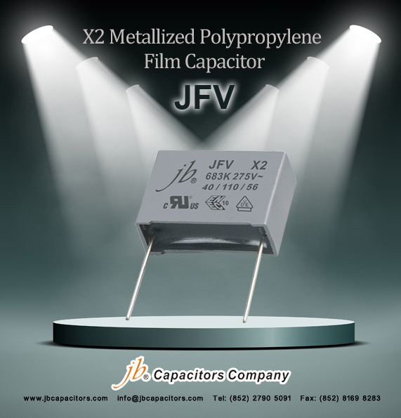
Maintenant nous sommes foyer sur favoriser notre série de JFV ! Cette série est pour le marché d'oversea, et employé couramment en ballasts électroniques, ventilateurs, éclairage, mètre de puissance, fournisseurs de puissance….application partout dans le monde. Achetez-vous des condensateurs du film X2 ? Bienvenue pour nous envoyer l'enquête et pour vérifier nos prix. Merci.
Série de JFV--Condensateurs de film de polypropylène métallisés par X2
Approbation de sûreté : Approbations de la CE et de TUV et d'UL.
Chaîne de capacité : 1000pF~2.2uF
Correspondance: Panasonic ECQU, Vishay MKP3382 275Vac, Wima MP3, Arcotronics R46, Pilkor PCX2 337,Epcos B81130, Evox Rifa PHE840M.
Délai d'exécution court : environ 5~7 semaines
Datasheet: http://www.jbcapacitors.com/pdf/JFV-X2-Metallized-Polypropylene-Film-Capacitor.pdf
2011-3-19 2:20:11
views
In aluminum electrolytic capacitors, the layer of insulating aluminum oxide on the surface of the aluminum plate acts as the dielectric, and it is the thinness of this layer that allows for a relatively high capacitance in a small volume. This oxide has a dielectric constant of 10, which is several times higher than most common polymer insulators. It can withstand an electric field strength of the order of 25 megavolts per meter which is an acceptable fraction of that of common polymers. This combination of high capacitance and reasonably high voltage result in high energy density.
Most electrolytic capacitors are polarized and require one of the electrodes to be positive relative to the other; they may catastrophically fail if voltage is reversed. This is because a reverse-bias voltage above 1 to 1.5 V will destroy the center layer of dielectric material via electrochemical reduction. Following the loss of the dielectric material, the capacitor will short circuit, and with sufficient short circuit current, the electrolyte will rapidly heat up and either leak or cause the capacitor to burst, often in spectacularly dramatic fashion.
2011-3-18 2:13:31
views
rated capacitance (cr)
The rated capacitance of a capacitor is the value which is indicated upon it. The capacitance is measured at 1 kHz and +23°C.
rated voltage (ur)
The rated voltage is the maximum direct voltage or the maximum RMS alternating voltage which may be applied continuously to the terminals of the capacitor at any temperature within the rated temperature range.
2011-3-17 2:24:19
views
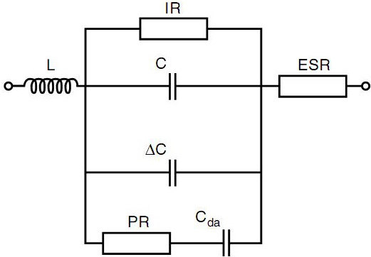
C = nominal value of the capacitor
L = inductance (leads, metallization, winding)
ESR = equivalent series resistance (leads, metallization, metal spraying)
IR = insulation resistance (properties of the dielectric material)
∆C = capacitance change (depending on changes in temperature, DC voltage and/or frequency)
PR = dielectric polarization resistance
Cda = dielectric absorption
2011-3-16 2:26:9
views
Capacitors loaded with pulses with fast rise or fall times (high dU/dt) will be exposed to high current pulses. In order not to overload the internal connections the current must be limited. The current limits for a specifc type are dependent upon:
- Amplitude and form of the pulse
- Rated voltage of the capacitor
- Capacitance
- Geometrical configuration of the winding
dU/dt = UR/(R x C)
UR = Rated voltage
R = Discharge resistor
C = Rated capacitance
2011-3-15 2:27:44
views
The reliability of a capacitor is mainly a function of:
- The construction; dielectric material and its thickness
- The manufacturing process
- The application; electrical stress and temperature
