2011-4-29 10:17:53
views
In theory, capacitors can be coupled both in series and parallel. If you need a 100MF cap and have two at 50MF, you can connect them in parallel, and that will give you 100MF (and same voltage rating as each). If you couple them in series, you get half the capacitance, and double voltage rating. But coupling electrolytic capacitors in series to get higher voltage rating must generally be discouraged. For this to work, you must be sure that the two (or more) caps share the voltage load properly; a resistor network can augment this, but if leakage currents are markedly different or the capacitors age differently, you are looking at a potential disaster, so do this only as a last resort, if at all.
2011-4-26 22:4:41
views
As already mentioned, never go below the voltage rating of the original part. Standards in voltage ratings have changed over the years, so you may not be able to find an exact replacement for the 250V capacitor you want to replace. Instead use 270V or even more. The only adverse effects of using a too high rating is price and, maybe, physical size; small problems compared to the risk of a capacitor impersonating a large firecracker inside your equipment!
Same is true of capacitance values: Standards have changed, and instead of old values like 15MF, 32MF, 50MF, etc, you will find 16, 33, 67, and such. The capacitance values of electrolytic capacitors are normally not very critical to the circuitry function, especially not in filters. A good rule of thumb is to go for the range between -20% to +100% of the original value, of course choosing a value as close as you can get.
There is a caveat here: If those capacitors have already been changed once, the values you look at may already deviate from the original values. If a 260V 40MF capacitor has sometime along the route been replaced with a 450V 67MF, you could be heading for problems; a 650V 100MF replacement will probably work, but we are getting out of bounds (oversize filter caps put extra strain on rectifier tubes, not to mention the price). So it would be nice to make a rough calculation to see if the value we are aiming for is reasonable.
2011-4-25 16:9:57
views
Aluminum electrolytic capacitors have a bi-polar structure. This is marked on the body of the capacitor. A capacitor must not be mounted with reversed polarity. The application of an AC or reverse voltage may cause a short circuit or damage the capacitor. Bi-polar capacitors must not be used in AC applications, where the polarity may be reversed in the circuits or is unknown.
jb SMD Aluminum Electrolytic Capacitor Product List
JCS - 2000H at 85°C SMD Aluminum Electrolytic Capacitor
JCK - 1000H at 105°C SMD Aluminum Electrolytic Capacitor
SMD aluminum electrolytic capacitors, jb Capacitors provides the most common series: 2000h at 85°C SMD aluminum electrolytic capacitors and 1000h at 105°C SMD aluminum electrolytic capacitors. jb Capacitors sell very competitive prices and our monthly output for SMD aluminum electrolytic capacitors can reach 30 millions units.
2011-4-22 16:4:8
views
The typical temperature range for aluminum electrolytic capacitors is –40 °C to 85 °C or 105 °C. Capacitance varies about +5% –40% over the range with the capacitance loss all at cold temperatures. Capacitors rated –55 °C generally only have –10 % to –20 % capacitance loss at –40 °C. Cold temperature performance for rated voltages of 300 V and higher is often worse, and temperature performance varies by manufacturer.
2011-4-20 15:55:3
views
Aluminum Electrolytic Capacitors capacitor element is wound on a winding machine with spindles for one-to-four separator papers, the anode foil, another set of one-to-four separator papers and the cathode foil. These are wound into a cylinder and wrapped with a strip of pressure-sensitive tape to prevent unwinding. The separators prevent the foils from touching and shorting, and the separators later hold the reservoir of electrolyte.
Before or during winding aluminum tabs are attached to the foils for later connection to the capacitor terminals. The best method is by cold-welding of the tabs to the foils with tab locations microprocessor controlled during winding so that the capacitor element’s inductance can be less than 2 nH. The older method of attachment is by staking, a process of punching the tab through the foil and folding down the punched metal. Cold welding reduces short-circuit failures and performs better in high-ripple current and discharge applications in which the individual stakes may fail from high current like buttons popping off one at a time from a fat-man’s vest.
2011-4-19 11:55:32
views
Aluminum Electrolytic Capacitor are connected in series, back-to-back with the positive terminals or the negative terminals connected, the resulting single capacitor is a non-polar capacitor with half the capacitance. The two capacitors rectify the applied voltage and act as if they had been bypassed by diodes. When voltage is applied, the correct-polarity capacitor gets the full voltage. In non-polar aluminum electrolytic capacitors and motor-start aluminum electrolytic capacitors a second anode foil substitutes for the cathode foil to achieve a non-polar capacitor in a single case.
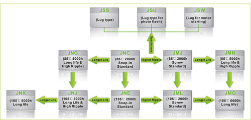
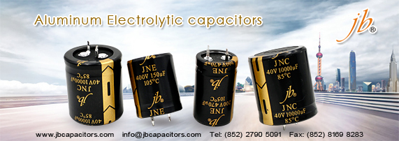
jb Capacitors markets Aluminum Electrolytic Capacitors, including JNC, JNE ,JNG ,JNJ , JNK , JMJ ……The following Picture shows our Aluminum Electrolytic Capacitors. For the detailed information ,We introduced in our website www.jbcapacitors.com .If necessary, you can contact our sales directly. I am sure you can get your satisfaction.
2011-4-15 15:59:12
views
An Integrated Circuit [IC] is normally decoupled using one bypass capacitor from 0.01uf to 0.1uf.Using the graph below, the 0.1uf response would result in the first dip at f1 followed by the dotted single line.
Placing a 0.01uf capacitor in parallel with the first cap also provides the second dip at f2 increasing the frequency response of the pair of caps.
The graphic above shows the benefit of placing two different value capacitors in parallel.
The impedance is reduced across a band of frequencies, adding the two nulls.
The first null is developed from the larger value capacitor, and the second null from the smaller value capacitor.
Placing a large value Tantalum capacitor next to a smaller value ceramic will cover a wide range of frequencies.
Placing two ceramic capacitors, a decade apart in value, in parallel will have the same effect but over a different frequency range.
2011-4-13 12:25:15
views
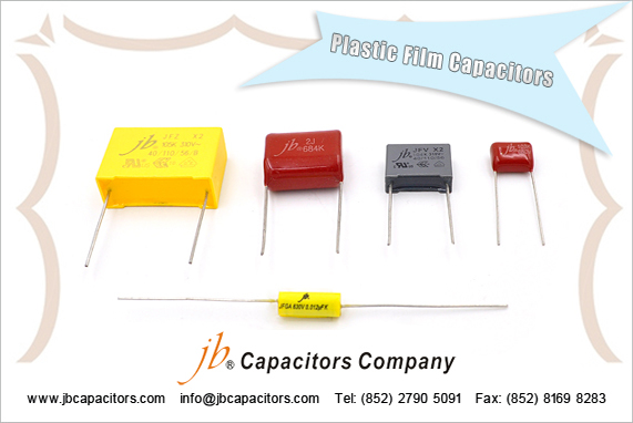
Film Capacitors are Non polarized, and may be used in AC or DC circuits.
Typical values range form 1000pF to 1uF for Polyerster Film, and 0.01uF to 18uF for Metallized Film capacitors. Standard Film Capacitor values change in multiples of 10, 12, 15, 18, 22, 27, 33, 39, 47, 56, 68, 82.
Normal Temperature Coefficient [TC] for Film Capacitors is +7%.
- Mylar: has a wide temperature change of 20% over -55 to +125°C. Moisture absorption is half that of paper.
Mylar is the same as polyester. The term Mylar is a trade name. - Polycarbonate: Out performs Mylar in all areas. Low Power factor, works best with AC. Polycarbonate has a low temperature drift (graph below), dissipation factor, and dielectric absorption. Use polyphenylene sulfide as a possible replacement.
- Polyester: Replaces paper for many applications, and smaller in size. Polyester does not have the moisture problem that paper does, but does have a worse tolerance, at 20% ~ over -55 to +125°C. May also be called PETE, or PETP. The Polyester Dielectric has an Absorption of around 0.20%.
- Polypropylene: It has negative temperature coefficient.
- Polysulfone: Has a very high operating temperature of +170°C.
- Polystyrene: Will only work to +65°C. It has a flat to negative temperature coefficient.
- Teflon: Has a very high operating temperature of +170°C.
2011-4-11 21:22:52
views
jb Capacitors manufactures and markets SMD Aluminum Electrolytic Capacitor. 2000 hours at 85°C Chip Aluminum Electrolytic Capacitor is one of the most common series. We sell quite good prices, high quality and with short lead time.
Load Life:After 2000 hours application of rated voltage at 85℃, capacitors meet the characteristics
| Capacitance Change | Within ± 20% of initial value (Within ± 25% of initial value for 4V) |
| Dissipation Factor | 200% or less of initial specified value |
| Leakage Current | Initial specified value or less |
2011-4-8 23:22:39
views
In many applications capacitors need not be specified to tight tolerance (they often need only to exceed a certain value); this is particularly true for electrolytic capacitors, which are often used for filtering and bypassing. Consequently capacitors, particularly electrolytics, often have a tolerance range of ±20% and need to be available only within E6 (or E3) series values.
| Series | Values |
| E3 | 1.0 | | | | 2.2 | | | | 4.7 | | | |
| E6 | 1.0 | | 1.5 | | 2.2 | | 3.3 | | 4.7 | | 6.8 | |
| E12 | 1.0 | 1.2 | 1.5 | 1.8 | 2.2 | 2.7 | 3.3 | 3.9 | 4.7 | 5.6 | 6.8 | 8.2 |
Other types of capacitors, e.g. ceramic, can be manufactured to tighter tolerances and are available in E12 or closer-spaced values (e.g. 47 pF, 56 pF, 68 pF).
With the introduction of S.I. submultiples of micro, nano, and pico, it became customary to specify capacitors with a number between 1 and 999 followed by farad, microfarad, nanofarad, or picofarad. While supercapacitors of up to 5,000 farads are produced, it is not usual to use kilofarad or millifarad.


