2022-8-12 9:55:34
views
For some customers look for smaller size SMD Aluminum electrolytic capacitors for their application, our JCT and JCX series can meet the needs.
JCT and JCX series can be used on general application, they can be used on the board with space economic.
JCT - 2000H to 3000H at 105°C, Small Size SMD Aluminum Electrolytic Capacitor
JCX - 2000H to 5000H at 105°C, Small Size SMD Aluminum Electrolytic Capacitor
Operating temperature: -55C~ +105C
Voltage range:6.3V ~ 50V.DC
Capacitance range:10 ~ 2200μF
Capacitance tolerance:±20% at 120Hz, 20C
Leakage current: The greater value of either 0.01CV or 3μAr μA/after 2minutes (max)

2022-8-1 14:49:35
views
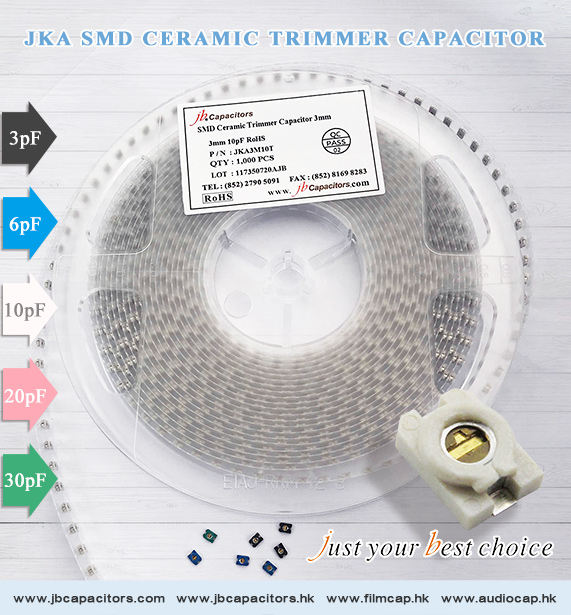
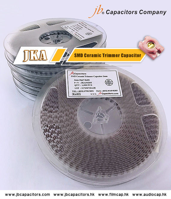
Recently the market lack of SMD Ceramic Trimmer Capacitor very much, and the delivery time is very long.
We keep some stock for this series, and make sure high quality. Are you looking for this item? Please contact us asap.
JKA - SMD Ceramic Trimmer Capacitor
Features:
• Ultra miniature size with external dimensions of 3.2(W) x 4.5(L) x 1.5(T)mm
• Color coded case permits easy identification
• Very good Q and high resonant frequency
• Designed for reflow soldering
• Lowest capacitance drift
• Sealed construction prevents the penetration of Flux and Dust
| JKA3M03T | JKA3M06T | JKA3M10T | JKA3M20T | JKA3M30T |
| 3pF | 6pF | 10pF | 20pF | 30pF |
| Black | Blue | Ivory | Pink | Green |
2021-6-2 14:20:12
views
A trimmer capacitor is a variable capacitor used for initial calibration and recalibration of equipment. It is commonly mounted directly on a PCB and accessed only by professional repairmen, not the end-user.
Characteristics
Voltage rating, capacitance range, polarity.
Trimmer capacitors can be rated for voltages up to 300 volts, although voltage ratings of up to 100 volts are much more common. Since trim caps are variable capacitors, they come in a capacitance range rather than a
single capacitance value. The minimum capacitance is usually between 0.5 pF and 10 pF, while the maximum capacitance is usually between 1 pF and 120 pF. The actual capacitance value can be varied between the
minimum and maximum capacitance values for a given trimmer capacitor, but it can never be set to zero. It is worth noting that trimmer capacitors are not polarized.
Tolerances and accuracy
Trimmer capacitors do not boast a good capacitance value tolerance. Sometimes, the tolerances can be as high as -0 to +100%. This means that a trimmer capacitor can have a maximum capacitance two times larger
than nominal. However, bad tolerances do not pose a great problem to engineers because trimmer capacitors are variable. Even if the maximum value is different between individual capacitors, they can still be set by turning the screwdriver a certain angle. Accuracy depends mostly on the operator, as he can choose to spend more time in order to set the capacitor to a desired value. Often, trimmer capacitors are set by robots instead of human operators, and they can achieve much better precision. In order to achieve a better accuracy, it is advised to use a non-metallic tool, since metal screwdrivers will introduce a source of capacitance that will vary the capacitance value when the tool is moved away from the capacitor.
Construction and properties of trimmer capacitors
There are two types of trimmer capacitors: air trimmer capacitor and ceramic trimmer capacitor. These two types use different materials as the dielectric. Both types use rotating action to change the capacitance value.
The construction of trimmer capacitors is similar to the construction of their larger variant, the variable capacitor. Trimmer capacitors can be made of semi-circular metal plates. One is fixed, while the other can be rotated using a screwdriver. The user changes the capacitance by rotating the shaft and increasing or reducing the amount of overlap between the two plates. Gear mechanisms may be used to improve the precision by allowing multiple turns between the lowest and highest settings.
Another way to make a trimmer capacitor is to place a metallic screw in a non-conductive threaded cylinder. The screw represents one electrode, while the other is located at the base of the cylinder. By rotating the screw, the distance between the two plates is varied which results in a change of capacitance. This construction is used in RF and microwave applications.
2019-12-31 14:27:50
views
Christmas is just right the corner, have you finish decorating your Christmas tree and finish raping up your presents?
jb Capacitors Company is celebrating this special holiday of the year with all of our clients. Provide a variety of capacitors and launching more products is how we celebrate this time of the year. You can find mostly all of
the capacitors you need with finest price here. Send us your product list and we will handle the rest for you so you can enjoy your holiday without any worries.
Visit our website for more information or send us message for more details.
http://www.jbcapacitors.com/products.html

2011-7-11 10:43:35
views
For capacitors in parallel
Capacitors in a parallel configuration each have the same applied voltage. Their capacitances add up. Charge is apportioned among them by size. Using the schematic diagram to visualize parallel plates, it is apparent that each capacitor contributes to the total surface area.
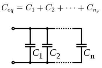
Several capacitors in parallel.
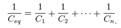
For capacitors in series
Connected in series, the schematic diagram reveals that the separation distance, not the plate area, adds up. The capacitors each store instantaneous charge build-up equal to that of every other capacitor in the series. The total voltage difference from end to end is apportioned to each capacitor according to the inverse of its capacitance.

Several capacitors in series.
The entire series acts as a capacitorsmaller than any of its components.
Capacitors are combined in series to achieve a higher working voltage, for example for smoothing a high voltage power supply. The voltage ratings, which are based on plate separation, add up. In such an application, several series connections may in turn be connected in parallel, forming a matrix. The goal is to maximize the energy storage utility of each capacitor without overloading it.
For more products information please check: http://www.jbcapacitors.com/
2011-4-29 10:17:53
views
In theory, capacitors can be coupled both in series and parallel. If you need a 100MF cap and have two at 50MF, you can connect them in parallel, and that will give you 100MF (and same voltage rating as each). If you couple them in series, you get half the capacitance, and double voltage rating. But coupling electrolytic capacitors in series to get higher voltage rating must generally be discouraged. For this to work, you must be sure that the two (or more) caps share the voltage load properly; a resistor network can augment this, but if leakage currents are markedly different or the capacitors age differently, you are looking at a potential disaster, so do this only as a last resort, if at all.
