jb Capacitor Bypassing using multiple capacitors

An Integrated Circuit [IC] is normally decoupled using one bypass capacitor from 0.01uf to 0.1uf.Using the graph below, the 0.1uf response would result in the first dip at f1 followed by the dotted single line.

Placing a 0.01uf capacitor in parallel with the first cap also provides the second dip at f2 increasing the frequency response of the pair of caps.

The graphic above shows the benefit of placing two different value capacitors in parallel.

The impedance is reduced across a band of frequencies, adding the two nulls.

The first null is developed from the larger value capacitor, and the second null from the smaller value capacitor.

Placing a large value Tantalum capacitor next to a smaller value ceramic will cover a wide range of frequencies.

Placing two ceramic capacitors, a decade apart in value, in parallel will have the same effect but over a different frequency range.

jb Plastic Film Capacitor—Dielectric Types

Film Capacitors are Non polarized, and may be used in AC or DC circuits.
Typical values range form 1000pF to 1uF for Polyerster Film, and 0.01uF to 18uF for Metallized Film capacitors. Standard Film Capacitor values change in multiples of 10, 12, 15, 18, 22, 27, 33, 39, 47, 56, 68, 82.

Normal Temperature Coefficient [TC] for Film Capacitors is +7%.

  • Mylar: has a wide temperature change of 20% over -55 to +125°C. Moisture absorption is half that of paper.
    Mylar is the same as polyester. The term Mylar is a trade name.
  • Polycarbonate: Out performs Mylar in all areas. Low Power factor, works best with AC. Polycarbonate has a low temperature drift (graph below), dissipation factor, and dielectric absorption. Use polyphenylene sulfide as a possible replacement.
  • Polyester: Replaces paper for many applications, and smaller in size. Polyester does not have the moisture problem that paper does, but does have a worse tolerance, at 20% ~ over -55 to +125°C. May also be called PETE, or PETP. The Polyester Dielectric has an Absorption of around 0.20%.
  • Polypropylene: It has negative temperature coefficient.
  • Polysulfone: Has a very high operating temperature of +170°C.
  • Polystyrene: Will only work to +65°C. It has a flat to negative temperature coefficient.
  • Teflon: Has a very high operating temperature of +170°C.

jb SMD Aluminum Electrolytic Capacitor --JCS - 2000H at 85°C

jb Capacitors manufactures and markets SMD Aluminum Electrolytic Capacitor. 2000 hours at 85°C Chip Aluminum Electrolytic Capacitor is one of the most common series. We sell quite good prices, high quality and with short lead time.

Load Life:After 2000 hours application of rated voltage at 85℃, capacitors meet the characteristics

Capacitance Change Within ± 20% of initial value (Within ± 25% of initial value for 4V)
Dissipation Factor 200% or less of initial specified value
Leakage Current Initial specified value or less

jb Capacitor Standard Values

In many applications capacitors need not be specified to tight tolerance (they often need only to exceed a certain value); this is particularly true for electrolytic capacitors, which are often used for filtering and bypassing. Consequently capacitors, particularly electrolytics, often have a tolerance range of ±20% and need to be available only within E6 (or E3) series values.

Series Values
E3 1.0       2.2       4.7      
E6 1.0   1.5   2.2   3.3   4.7   6.8  
E12 1.0 1.2 1.5 1.8 2.2 2.7 3.3 3.9 4.7 5.6 6.8 8.2

Other types of capacitors, e.g. ceramic, can be manufactured to tighter tolerances and are available in E12 or closer-spaced values (e.g. 47 pF, 56 pF, 68 pF).

With the introduction of S.I. submultiples of micro, nano, and pico, it became customary to specify capacitors with a number between 1 and 999 followed by farad, microfarad, nanofarad, or picofarad. While supercapacitors of up to 5,000 farads are produced, it is not usual to use kilofarad or millifarad.

jb Electrolytic capacitor Leakage

Although Electrolytic Capacitors have much higher levels of capacitance for a given volume than most other capacitor technologies, they can also have a higher level of leakage. This is not a problem for most applications, such as when they are used in power supplies. However under some circumstances they are not suitable. For example they should not be used around the input circuitry of an operational amplifier. Here even a small amount of leakage can cause problems because of the high input impedance levels of the op-amp. It is also worth noting that the levels of leakage are considerably higher in the reverse direction.

jb Aluminum Electrolytic Capacitor Polarisation

Unlike many other types of capacitor, electrolytic capacitors are polarised and must be connected within a circuit so that they only see a voltage across them in a particular way. The capacitors themselves are marked so that polarity can easily be seen. In addition to this it is common for the can of the capacitor to be connected to the negative terminal.

It is absolutely necessary to ensure that any electrolytic capacitors are connected within a circuit with the correct polarity. A reverse bias voltage will cause the centre oxide layer forming the dielectric to be destroyed as a result of electrochemical reduction. If this occurs a short circuit will appear and excessive current can cause the capacitor to become very hot. If this occurs the component may leak the electrolyte, but under some circumstances they can explode. As this is not uncommon, it is very wise to take precautions and ensure the capacitor is fitted correctly, especially in applications where high current capability exists.

jb Capacitors

Capacitor plague (also known as bad capacitors) is an ongoing problem with premature failure of large numbers of electrolytic capacitors of certain brands. Capacitors are used in various electronics equipment, particularly motherboards, video cards, compact fluorescent lamp ballasts, LCD monitors, and power supplies of personal computers. The first flawed capacitors were seen in 1999, but most of the affected capacitors were made in the early to mid 2000s. News of the failures (usually after a few years of use) forced most manufacturers to repair the defects and stop using the capacitors, but some bad capacitors were still being sold or used in equipment as of early 2007[update], and faults are still being reported as of 2011[update].Reference computer user reports on badcaps.net.

A serious quality control problem is that the issue only manifests after use over a period of time; poor quality electrolytic capacitors have the same measurable parameters as good ones when new. Only extensive accelerated life testing with high ripple currents and high operating temperatures can identify inferior components. After some normal use the bad capacitors fail predictably far sooner than normal end-of-life; most electronic components do not systematically fail in this way.

jb Aluminum Electrolytic Capacitors Construction

The plates of an electrolytic capacitor are constructed from conducting Aluminum foil. As a result they can be made very thin and they are also flexible so that they can be packaged easily at the end of the production process. The two plates, or foils are slightly different. One is coated with an insulating oxide layer, and a paper spacer soaked in electrolyte is placed between them. The foil insulated by the oxide layer is the anode while the liquid electrolyte and the second foil act as cathode.

There are two geometries that are used for the connection leads or tags. One is to use axial leads, one coming from each circular face of the cylinder. The other alternative is to use two radial leads or tags, both of which come from the same face of the cylinder.

The lead styles give rise to the descriptions used for the overall capacitors. Descriptions of axial and radial will be seen in the component references.

jb Capacitor Construction

Capacitors have thin conducting plates (usually made of metal), separated by a layer of dielectric, then stacked or rolled to form a compact device.

Many types of capacitors are available commercially, with capacitance ranging from the picofarad, microfarad range to more than a farad, and voltage ratings up to hundreds of kilovolts. In general, the higher the capacitance and voltage rating, the larger the physical size of the capacitor and the higher the cost. Tolerances in capacitance value for discrete capacitors are usually specified as a percentage of the nominal value. Tolerances ranging from 50% (electrolytic types) to less than 1% are commonly available.

Another figure of merit for capacitors is stability with respect to time and temperature, sometimes called drift. Variable capacitors are generally less stable than fixed types.

jb Non-ideal properties of practical capacitors-- Breakdown voltage

The breakdown voltage of the dielectric limits the power density of capacitors. For a particular dielectric, the breakdown voltage is proportional to the thickness of the dielectric.

If a manufacturer makes a new capacitor with the same dielectric as some old capacitor, but with half the thickness of the dielectric, the new capacitor has half the breakdown voltage of the old capacitor.

Because the plates are closer together, the manufacturer can put twice the parallel-plate area inside the new capacitor and still fit it in the same volume (capacitor size) as the old capacitor. Since the capacitance of a parallel-plate capacitor is given by:

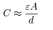
this new capacitor has 4 times the capacitance as the old capacitor.

Since the energy stored in a capacitor is given by:
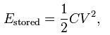
this new capacitor has the same maximum energy density as the old capacitor.