2011-7-13 16:55:30
views
安规电容是指用于这样的场合:即电容器失效后,不会导致电击,不危及人身安全.它包括了X电容和Y电容。
X电容是跨接在电力线两线 (L-N) 之间的电容,一般选用金属化薄膜电容;Y电容是分别跨接在电力线两线和地之间 (L-E, N-E) 的电容,一般是成对出现。
基于漏电流的限制,Y电容值不能太大,一般X电容是uF级,Y电容是nF级。X电容抑制差模干扰,Y电容抑制共模干扰。
| 安规电容安全等级 | 应用中允许的峰值脉冲电压 | 过电压等级 (IEC664) |
| X1 | >2.5kV ≤4.0kV | Ⅲ |
| X2 | ≤2.5kV | Ⅱ |
| X3 | ≤1.2kV | —— |
| | | |
| 安规电容安全等级 | 绝缘类型 | 额定电压范围 |
| Y1 | 双重绝缘或加强绝缘 | ≥ 250V |
| Y2 | 基本绝缘或附加绝缘 | ≥150V ≤250V |
| Y3 | 基本绝缘或附加绝缘 | ≥150V ≤250V |
| Y4 | 基本绝缘或附加绝缘 | <150V |
Y电容的电容量必须受到限制,从而达到控制在额定频率及额定电压作用下,流过它的漏电流的大小和对系统EMC性能影响的目的。
GJB151规定Y电容的容量应不大于0.1uF。Y电容除符合相应的电网电压耐压外,还要求这种电容器在电气和机械性能方面有足够的安全余量,避免在极端恶劣环境条件下出现击穿短路现象,
Y电容的耐压性能对保护人身安全具有重要意义。

2011-7-11 10:43:35
views
For capacitors in parallel
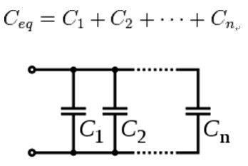
Capacitors in a parallel configuration each have the same applied voltage. Their capacitances add up. Charge is apportioned among them by size. Using the schematic diagram to visualize parallel plates, it is apparent that each capacitor contributes to the total surface area.

Several capacitors in parallel.
For capacitors in series
Connected in series, the schematic diagram reveals that the separation distance, not the plate area, adds up. The capacitors each store instantaneous charge build-up equal to that of every other capacitor in the series. The total voltage difference from end to end is apportioned to each capacitor according to the inverse of its capacitance.

Several capacitors in series.
The entire series acts as a capacitorsmaller than any of its components.

Capacitors are combined in series to achieve a higher working voltage, for example for smoothing a high voltage power supply. The voltage ratings, which are based on plate separation, add up. In such an application, several series connections may in turn be connected in parallel, forming a matrix. The goal is to maximize the energy storage utility of each capacitor without overloading it.
For more products information please check: http://www.jbcapacitors.com/
2011-7-8 22:22:44
views
CE word is from the French "Communate Europpene" from the initials, is the meaning of the European Community。"CE" mark is a safety certification mark, the manufacturer is considered open and the passport to enter the European market.
UL is in English Test by insurance Underwriter Laboratories Inc. UL secuity testing is the most authoritative, but also engages im community safety testing and identification of the larger non-governmental organizations.
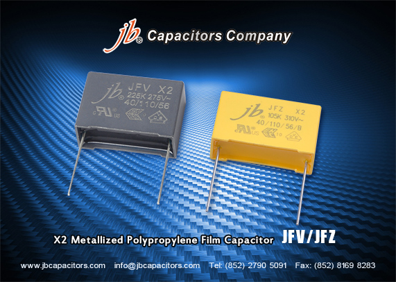
JFV-X2 Metallized Polypropylene Film Capacitor, is not only with above two approvals(CE& UL), but also with TUV approvals. That must can help to promote this capacitor in your market.
Do you use the X2 safety capacitors ? For more info, welcome to visit "jbcapacitors" production lines: http://www.jbcapacitors.com/Plastic-Film-Capacitors/
2011-7-6 22:14:51
views
In order to meet some customers' urgent request, jb capacitors company plan to sell stock X2 film capacitors from July.
Now we have below stock X2 Metallized Polypropylene Film Capacitors, welcome to ask for quote
JFV-X2 Metallized polypropylene film capacitor, cross to Epcos B81130, Vishay MKP3382, Kemet R46,etc.
0.1uF 275VAC +/-10% P:15mm Bulk RoHS Part#: JFV0A1104K150000B, .
0.22uF 275VAC +/-10% P:15mm Bulk RoHS Part#: JFV0A1224K150000B
X2 film capacitors widely used in powersupply, amplifier, electronic ballast, white goods, automotive etc..
jb capacitors JFV series X2 film capacitor is one of the most strong series, best seller, with jb UL,TUV,CE approvals.
Stock samples & goods are available! First come first served!
2011-7-4 16:1:55
views
Kindly note Mylar Polyester Film capacitor can be used in Home Refrigerator with 1200V high voltage and value (1000pF /2200pF /2700pF /3300pF ).
JFA--Mylar polyester film capacitors, green capacitors.
1000pF 1200V
2200pF 1200V
2700pF 1200V
3300pF 1200V
Datasheet: http://www.jbcapacitors.com/pdf/JFA-Mylar-Polyester-Film-Capacitor.pdf
What is your application ? What kind of capacitors do you use ?
2011-7-1 15:33:53
views
Film capacitors mainly used in electronics, home appliance, communication, electrified railway, HEV(Hybrid Electric Vehicle), wind power generation, solar electrical energy generation etc..
As the demand of film capacitors for frequency home appliance is bigger than that of common home appliance, its advantages of energy conservation and environmental protection are more and more popular, future market is much bigger. After Japanese earthquake, frequency home appliance market much bigger than CFL, and the development potential even bigger.
With the development of technology, electronics, home appliances, communications and other industries replacement cycles are getting shorter, and film capacitors with its good electrical performance and high reliability, become the indispensable electronics components for promoting and upgrading of the above industries.With the next few years, digital, information technology, network construction and further development of countries in the power grid construction, electrification of railway construction, energy efficient lighting, hybrid cars, etc. to increase investment and consumer electronics products, upgrades, market demand for film capacitors will further show rapid growth trend
2011-6-29 15:25:11
views
When you use a capacitor after prolonged storage. you should pay attention.
An Aluminium Electrolytic Capacitor which has been stored for a long period of time tends to give increased leakage current.
Accordingly, whenever you use a capacitor that has been stored a while, make sure to gradually increase the voltage to the rated value. Since the leakage current tends to be higher with higher storage
atmosphere temperatures. store the units at a location with storage temperatures of -40 to 40C which is not exposed to direct sunlight.
2011-6-27 15:20:51
views
JMQ is one of our screw type aluminium electrolytic capaciotrs. it can be used in electrical source panel.
And one of the panel function is that it can control pulse current discharge in plasma generator device.
Pls. click the link for the specification.
http://www.jbcapacitors.com/pdf/JMQ-5000H-at-105-Screw-Aluminum-Electrolytic-Capacitor.pdf
2011-6-27 15:19:17
views
Mylar Polyester film has a lot of mechanical, di-electrical, excellent optical and physical strength and so it is been widely used in many fields. It is mainly used for the purpose of insulation and is used in electrical equipment, appliance, and membrane switch.
The features of Mylar Polyester film capacitor are as follows. It is train-and tear-resistant, dimensionally stable and has excellent electrical properties. This material has good heat-and cold-resistant properties and is resistant to common solvents. The main application of Mylar Polyester film capcitor is that it is used as intermediate and top layer insulation in transformers, chokes and relay coils. Furthermore, it is used as slot and phase insulation, as a cover slide, in electric machinery, generators, as insulating layer for magnets and in electrical equipment been used..
jb capacitors company has such product, JFA—Mylar Polyester Film Capacitor, welcome to visit website www.jbcapacitors.com for further details.


