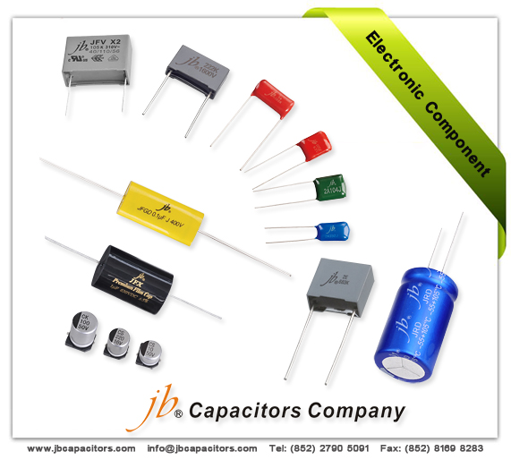
jb condensateur--composant électronique
Si vous êtes spécialisés en composant électronique et vous avez les demandes en condensateur, si vous êtes un distributeur qui cherche les condensateur pour votre client, si vous êtes un fabricant et vous cherchez un condensateur pour soutenir vos projets, vous pouvez cliquer ici
www.jbcapacitors.hk et découvrir jb capacitors.
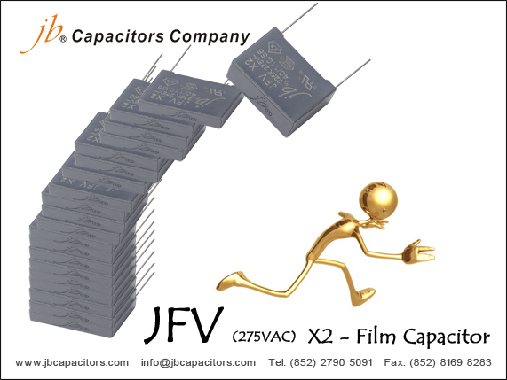
Vous allez trouver jb capacitors est très fort en toutes les séries de MKT,MKP Films condensateur, JFV-X2 Métallisé, Polypropylène Films condensateur, et JFB sont les meilleurs ventes, et maintenant jb capacitors peut même offrir la série de JFQ, cette série est cessé l’année dernière a cause du manque de matière.
La série de JFQ est haute terminal Films condensateur en Chine, double faces Métallisé, Polypropylène Films condensateur, peu de fournisseur peut le fabriquer. Mais nous pouvons vous l’offrir avec un court délais de 5-6 semaines.
Type boîte avec tres petite taille et haute rayon de voltage et large rayon de capacité, il peut remplacer certain Epcos, Evox, Arcotronics Films condensateur.
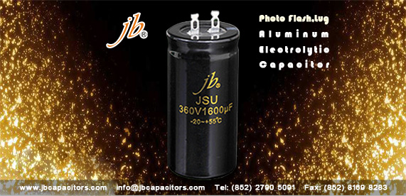
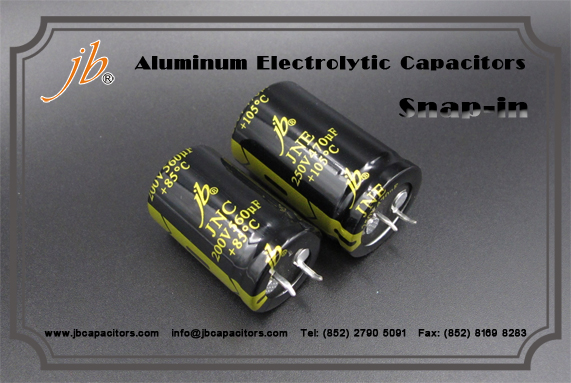
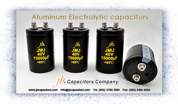
A part des différents type de condensateurs, nous somme aussi professionnel pour large can électronique aluminium Condensateurs, Snap-in, Screw, Lug type, SMD type standard. Nous attendons une l’occasion de vous présenter notre devis compétitive avec bon prix, court délais et haute qualités.