jb Capacitors JFV X2 Metallized Polypropylene Film Capacitors Stock Samples Avaliable
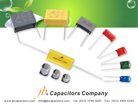
jb capacitors company is a professional manufacturer, produce film capacitors for more than 31 years.
X2 film capacitors is our best seller, price is very competitive, lead time is very short!
Now we have below stock samples, are you interested in? Welcome to send me your inquiry for quotation and ask for samples.
Cross Reference: Epcos B81130, Vishay MKP3362, Arcotronic R46, Panasonic ECQU, Philkor PCX2 335, Wima MKP 3 ...
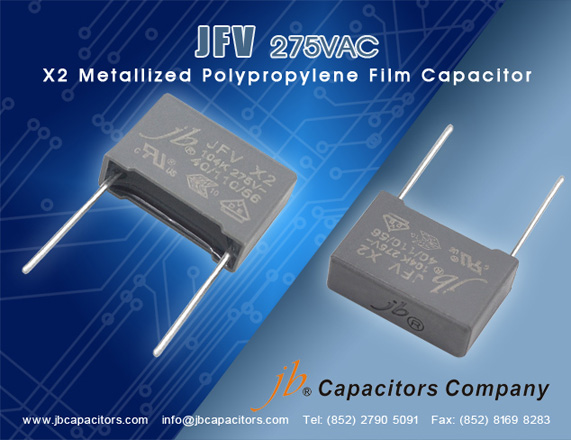
JFV-X2 Metallized Polypropylene Film Capacitor
- 0.1uF 275VAC +/-10% P:10mm Bulk RoHS
- 0.1uF 275VAC +/-10% P:15mm Bulk RoHS
- 0.068uF 275VAC +/-10% P:15mm Bulk RoHS
- 0.022uF 275VAC +/-10% P:10mm Bulk RoHS
- 0.15uF 275VAC +/-10% P:15mm Bulk RoHS
- 0.22uF 275VAC +/-10% P:22.5mm Bulk RoHS
- 0.33uF 275VAC +/-10% P:22.5mm Bulk RoHS
- 0.47uF 275VAC+/-10% P:22.5mm Bulk RoHS
- 0.68uF 275VAC +/-10% P:22.5mm Bulk RoHS
- 1uF 275VAC +/-10% P:22.5mm Bulk RoHS
- 2.2uF 275VAC +/-10% P:27.5mm Bulk RoHS
Looking forward to your reply, you can also send mail to us info@jbcapacitors.com.