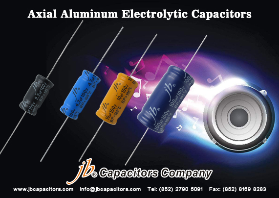
jb Capacitors best offer for Axial Audio capacitors

jb Capacitors Company is not only producing the capacitors in industry, but also for Audio product. Not matter you are home application or for business purpose, you can check our Audio series.

The most popular series is JFX series - Axial Premium Metallized Polypropylene Film Capacitors.
It can be used in Audio application with very good price. And it is the cheapest one among JFX, JSX, JPX and other audio series.

Please take a look on our website and datasheet for more information. 

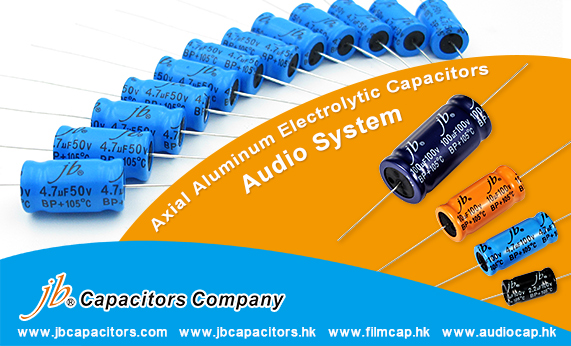
jb Capacitors Axial Aluminum Electrolytic Capacitors for Audio System

jb is expanding our market share on Audio, we have several capacitors series that are designed for Audio application. Not only film capacitors but also Aluminum Electrolytic Capacitors. Today, let’s check what series we have. For Axial type of Aluminum Electrolytic Capacitors, there are JAC,JAD,JAE,JAF series.

These four series have the same features including Load Life and Operating Temperature. And, what differences they have, they each have different Dissipation Factor. Please check their datasheet for more information. You can find all our information on our official website.

Series

Load Life

Operating Temperature Range (°C)

Description

JAC

1000 hours

105°C

DF at max 4% BP for Audio system

JAD

1000 hours

105°C

DF at max 5% BP for Audio system

JAE

1000 hours

105°C

DF at max 10% at 1KHz BP for Audio system

JAF

1000 hours

105°C

DF at max 10% BP at 120Hz for Audio system


jb Tell You Some Aluminum Electrolytic Capacitors' Features and Application

Aluminum electrolytic capacitors have always been a popular choice for power supply, due to its low cost. However, their life have limited , and easy to influenced by extreme conditions ,main problem is high temperature and low temperature. Aluminum Electrolytic capacitors is made by aluminum foil and electrolyte. This electrolyte will evaporate during the life of the capacitor, it will change its electrical properties step by step. If the capacitor fails, it will be violent reactions: release flammable, corrosive gases.

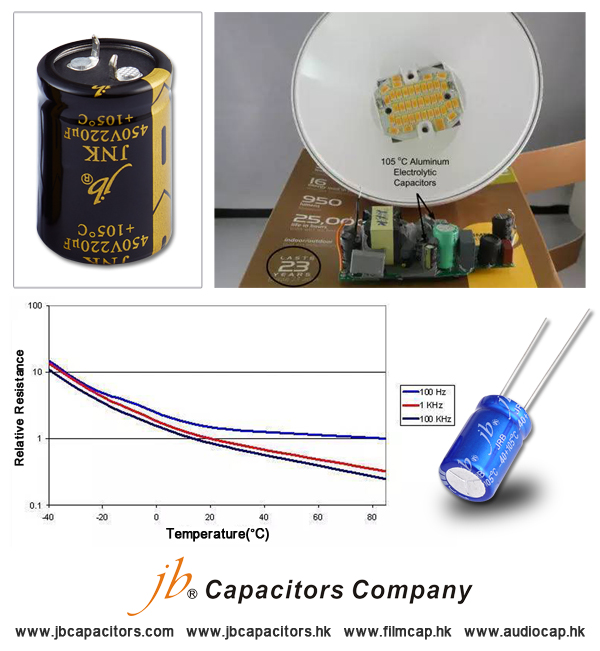
The electrolyte evaporation's speed all depend on capacitor temperature. Operating temperature dropped 10 degrees, the capacitor's life will be doubled. Usually, the capacitors' life usually means under maximum rated temperature. The typical rated life is 1000 hours at 105 degrees Celsius. In the application of LED which requirement life time 25000hours, the aluminum electrolytic capacitor will have problem. Cause if want to reach to 25000hours, the working temperature should not more than 65°C. But LED working temperature can reach to 125°C at most. Though some famous manufacturer declare their can reach. but aluminum electrolytic capacitors still is limited LED Lamp's life.

How to solve this problem? First, you may be chose to increase the rated voltage of the capacitor, to reduce the probability of electrolyte failure. However, the way will make the capacitor equivalent series resistance (ESR) more higher than before. Since the capacitor will generally have a high ripple current stress, so this high internal resistance will bring additional power consumption and increase the capacitor temperature. Failure rate will increases by increasing temperature. When the capacitor temperature is low, ESR increased dramatically. In this case,-40°C, the resistance increases by orders of magnitude. This will affect the power performance in many ways. If the capacitor is used for output of a switching power supply, the output ripple voltage was increased by orders of magnitude. Further, in the above zero frequency and the output capacitor ESR is formed, which allows an order of magnitude increase in the loop gain, which affects the control loop. This produces a stable oscillation power. In order to meet this strong vibration, the control loop will usually make a huge compromise in terms of space and operate at higher temperatures.

In short, the aluminum electrolytic capacitor is typically the lowest cost option. However, you will need to determine whether the application of its shortcomings adversely affected. Through its operating temperature you need to consider their longevity. meanwhile, you should appropriately reduce the rated voltage, so that you can achieve the lowest temperatures, and thus get the longest life. Finally, you need to understand the ESR range must be used so that you can properly design the control loop, to meet the ripple specifications.
 

jb Capacitors Company Released A Series of Axial Aluminum E-caps, Competitive Prices Available Now!!

Dear Friends,
Good news for you!
Recently, jb Capacitors Company developed few series of axial aluminum electrolytic capacitors, especially for audio system.
High quality commitment, competitive prices supported during Spring Season. Any interest, please don’t be hesitate to contact our sales for best quotation. 
We are ready here to offer you great services. 
Email: info@jbcapacitors.com

Feacture:

  • Bi-Polarized
  • 105”C 1000 hours
  • Different low Dissipation Fact MAX 4% at 1KHz/  MAX 5% at 1KHz/  MAX 10% at 1KHz/ or MAX 4% at 120Hz
  • High-quality crossover non-polar aluminum electrolytic capacitors

Application:

  • Specially produced for Cross-Over Networks with high fidelity audio system
  • Product mainly used: Tube Amplifiers, Audio and HiFI Systems, Audio Converters and Dividers (partials), Audio amp, Automotive Electronics Products, speaker and so on

PDF datasheet link:

http://www.jbcapacitors.com/pdf/JAC-Bi-Polarized-Axial-Aluminum-Electrolytic-Capacitors-For-Audio-System.pdf

http://www.jbcapacitors.com/pdf/JAD-Bi-Polarized-Axial-Aluminum-Electrolytic-Capacitors-For-Audio-System.pdf

http://www.jbcapacitors.com/pdf/JAE-Bi-Polarized-Axial-Aluminum-Electrolytic-Capacitors-For-Audio-System.pdf

http://www.jbcapacitors.com/pdf/JAF-Bi-Polarized-Axial-Aluminum-Electrolytic-Capacitors-For-Audio-System.pdf 

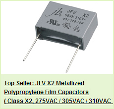
jb JFX--Audio Film Capacitors


jb capacitors produce below JFX series---Premium Metallized Polypropylene Film Capacitors, Axial lead.

Datasheet:http://www.jbcapacitors.com/pdf/JFX-Premium-Metallized-Polypropylene-Film-Capacitors-Axial.pdf

Leaflet:http://www.jbcapacitors.com/pdf/jb-Premium-Met-Cap-JFX.pdf

JFX--Audio film capacitors, top quality, excellent sound performance, used for amplifier, cross-over, loudspeakers...

1. Cross to Mundorf, Auricap,Erse, Mallory,Jantzen Audio, etc..audio capacitors.
2. Capacitance up to 300uF. very wide range.
3. Precise Tolerance: +/-10%, +/-5%, +/-2%, +/-1%.
4. Low MOQ: 100pcs each.
5. Top quality, excellent sound performances.
6. specially used for, amplifier, cross-over, loudspeakers.


jb Aluminum Electrolytic Capacitors Use Instructions

Aluminum electrolytic capacitors may cause an explosion, fire, or other serious trouble if not used under specified operating conditions. Please familiarize yourself with the instructions given below before using these capacitors Operating temperature and ripple current.

  • 1. Keep the operating temperature and ripple current in specified ranges. Applying an excessive current to a capacitor will overheat it, resulting perhaps in short-circuit, ignition, or other fatal fault.
  • 2. A capacitor is also a heating component itself. Please be on guard, remembering that it heats up the inside of the equipment. Run the unit under normal conditions and check the temperature of the surroundings of the capacitor.
  • 3. The permissible ripple current tends to decline with a rise in the atmosphere temperature (the temperature of the surroundings of the capacitor). Consider a permissible ripple current at the maximum predictable atmospheric temperature. Allow also for the changes in frequency.

Applied voltage and connections

  • 1. Capacitors have polarity. Applying a reverse voltage or AC voltage to a capacitor may cause a fire or other fatal fault.
  • 2. Use a bipolar capacitor for circuits whose polarity reverses. However, in this case, like any other case,refrain from using such a capacitor in AC circuit.
  • 3. When an AC component is superimposed on a DC voltage, prevent the peak value from exceeding the rated voltage. An excessive voltage may cause a short-circuit, fire, or other fatal fault.
  • 4. When connecting more than one capacitor in parallel, consider the resistance of the wiring. Establish the connections so that the wiring resistance will be equal at every capacitor.
  • 5. When more than one capacitor is connected in series, all capacitors must be of identical ratings. Then connect the balancing resistors in parallel. At that time, design the circuit so that the voltage levels applied to all capacitors become equal.Check that the voltages applied to capacitors do not exceed a rated voltage.
  • 6. Do not use such a capacitor for a circuit that is repeatedly charged and discharged quickly. If you are to use such a capacitor for a welding unit or for other charging and discharging purposes, use a capacitor designed on a separate basis.
  • 7. Even slow recharging may shorten the service life of a capacitor if its voltage changes greatly. Check it sufficiently as installed on a larger machine or consult Capsun.

Capacitor insulation

  • 1. Do not connect the blank terminal (reinforcing terminal) of a multi-terminal (three- or four-terminal) product of the snap-in type to another circuit. It may cause a short circuit.
  • 2. The external sleeve of the snap-in type has no insulator. If you need a sleeve with an insulator, consult Capsun.
  • 3. Ensure a completely open circuit between the case and the cathode terminal, and between the anode terminal and circuit pattern

Operating conditions

  • 1. A splash of water, salty water, oil or other electrically conductive liquid on a capacitor or using a capacitor when it has dew on it may cause a breakdown. Oil on the rubber sealing or safety vent may cause a decline in airtightness. Do not use a capacitor with liquid on it.
  • 2. Do not use or leave a capacitor in a place where there is a hydrogen sulfide, nitrous acid, sulfurous acid, chlorine, bromine, or other halide compound gas, ammonia, or other hazardous gas. The ingress of any of the aforementioned gases into a capacitor may corrode it. Avoid fumigating and spraying an insecticide as well.
  • 3. Do not use or leave a capacitor in a place exposed to ozone, ultraviolet ray, or radiation.
  • 4. Do not use a capacitor in a place where vibration or impact is excessive.

Installa tion Before installaton

  • 1. Do not reverse the polarity. Do not use a capacitor to which a reverse voltage is applied, even if it looks problem-free. It must be greatly damaged.
  • 2. Do not tighten the curled part (case sealed part) with a mounting fitting or otherwise stress it. Any such practice may cause a liquid leak or sleeve breakage.
  • 3. Dropping or otherwise impacting a capacitor may result in a decline in its electric performance,causing a breakdown. Therefore do not cause an impact on it.
  • 4. Do not reuse a capacitor which has been installed on a machine and energized. No capacitor can be reused except for those removed to measure their electric performance for a periodic checkup.

Method of installation

  • 1. Do not make the safety vent (cap side) of a screw terminal type face downwards. The safety vent may let the electrolyte or compound leak.
  • 2. Do not install a wiring or circuit pattern near the safety vent. When the safety vent is activated, the electrolyte may jet out, resulting in a fire or other secondary accident.
  • 3. Avoid installing a heating part around a capacitor or in back of a printed wiring board (beneath the capacitor).
  • 4. Do not hamper the activation of the safety vent. Above the safety vent (where a screw terminal type is installed on the terminal side, or snap-in type on the case bottom), allow for the following clearances.