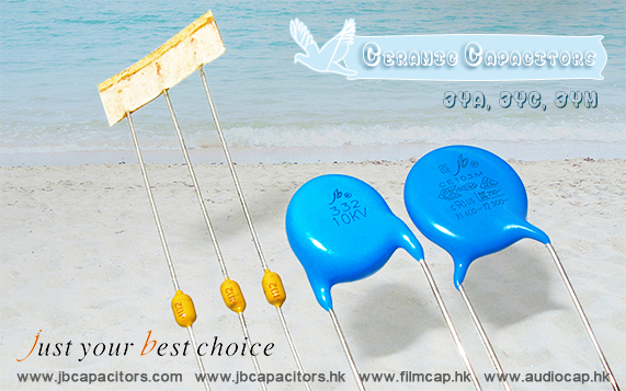
jb three kinds of ceramic capacitors
jb Capacitors manufactures and markets Ceramic Capacitors, Including X1 / CD Y1 400VAC and CE Y2 300AC Safety Standard Recognized Capacitors and 1KV, 2KV, 3KV,4KV, 5KV, 6KV, 8KV, 10KV, 15KV DC High Voltage Ceramic Capacitors, Multilayer (mono) Axial & Radial Ceramic Capacitors.
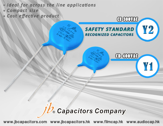
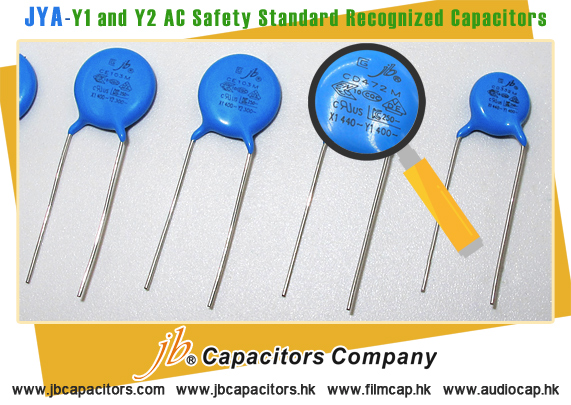
JYA - X1 / Y1(CD 400VAC) and Y2(CE 300VAC) Safety Standard Recognized Capacitors
The X1 / Y class safety-certified capacitors, used in line-to-ground (line bypass) applications, have voltages from 400VAC (Y1 series)/300VAC (Y2 series) and X1 series. Major features of these non-polar capacitors include capacitance range generally from 10pF to 10000pF; from 7.5mm to10mm lead spacing, high reliability, and kinked or straight lead configurations.
jb Class X1 / Y Safety Capacitors ideal for across the line applications, compact size, cost effective product, safety standards recognized.
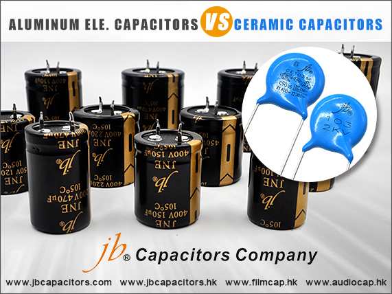
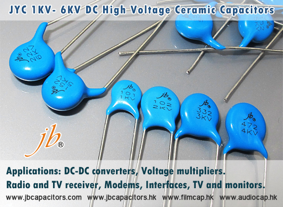
JYC – High Voltage Ceramic Radial Type Disc Capacitors
We designs and manufacture high quality Ultra-High Voltage Ceramic Capacitors Radial-Leaded Single Layer Disc (low loss type) Capacitors with blue coating epoxy resin, custom design radial lead disc ceramic capacitors as well as a variety of standard and custom High Voltage & High Capacitance value Ceramic Capacitors.
JYM - Multilayer (Mono) Ceramic Capacitors
Multilayer ceramic capacitors are available in a variety of physical sizes and configurations, including leaded devices and surface mounted chips. Leaded styles include molded and conformally coated parts with axial and radial leads. However, the basic capacitor element is similar for all styles. It is called a chip and consists of formulated dielectric materials which have been cast into thin layers, interspersed with metal electrodes alternately exposed on opposite edges of the laminated structure. The entire structure is fired at high temperature to produce a monolithic block which provides high capacitance values in a small physical volume. After firing, conductive terminations are applied to opposite ends of the chip to make contact with the exposed electrodes. Termination materials and methods vary depending on the intended use. Our JYM - Multilayer (Mono) Ceramic Capacitors, it can be made 25VDC and 100VDC. The leads can be bended for mounting purpose.
Above are our three kinds of Ceramic capacitors now. If you cannot find suitable products, please feel free to mail us.
We will try our best to find the substitution for you. Mail us to get more information!