2011-3-9 11:43:5
views
The following rules should be observed when handling aluminum electrolytic capacitors:
Any escaping electrolyte should not come into contact with eyes or skin.
If electrolyte does come into contact with the skin, wash the affected parts immediately with running water. If the eyes are affected, rinse them for 10 minutes with plenty of water. If symptoms persist, seek medical treatment.
...
2011-2-9 23:6:4
views
Aluminum is an abundant metallic chemical element which is widely used throughout the world for a wide range of products. Many consumers interact with some form of aluminum on a daily basis, especially if they are active in the kitchen.
The element has an atomic number of 13, and it is identified with the symbol Al on the periodic table of elements.
It is classified in the poor metals, sharing the property of extreme malleability with metals like tin and lead.
2011-1-29 21:27:56
views
Round Feed Through capacitors, in a skin tight plastic wrap with solderable ends (Style Q). The hole in the center of the capacitor is either a Teflon Tube, Paper Tube or Phenolic Tube ranging in sizes from just a wire to a large threaded stud to fit through. The majority of Feed Throughs are custom made to exact customer requirements. They are very popular in filter applications.
2011-1-21 2:4:52
views
[2]-3 Electrolyte
Aluminum electrolytic capacitors are made by layering the electrolytic paper between the anode and cathode foils, and then coiling the result. The process of preparing an electrode facing the etched anode foil surface is extremely difficult. Therefore, the opposing electrode is created by filling the structure with an electrolyte. Due to this process, the electrolyte essentially functions as the cathode. The basic functional requirements for the electrolyte are as follows:
- (1) Chemically stable when it comes in contact with materials used in the anode, cathode, and electrolytic paper.
- (2) Easily wets the surfaces of the electrode.
- (3) Electrically conductive.
- (4) Has the chemical ability to protect the anode oxide thin film and compensate for any weaknesses therein.
- (5) Low volatility even at high temperatures.
- (6) Long-term stability and characteristics that take into consideration such things as toxicity.
2011-1-20 1:52:14
views
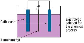
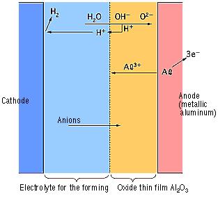
[2]-2 Forming (Anode Oxidation)
The "Forming" process is defined by creating an electrically insulating oxide (to provide the withstand voltage) on the aluminum surface by performing anode oxidation in the electrolytic solution used for the growth. The produced chemical film is used as the anode thin film.
The anode oxidation, as follow shown, is produced by applying a voltage to the submerged foil found in the electrolytic solution used for growing the oxide film. Generally, the electrolytic solution is an aqueous solution such as ammonium boric acid, ammonium phosphate, or ammonium adipic for acid.
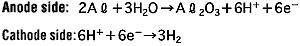
During the anode oxidation (DC electrolysis), AL2O3 is produced by a reaction between the water and the aluminum's Al3+ ions. The thickness of the grown thin film is nearly proportional to the applied voltage] with approximately 1.0 to 1.4 nm per volt. The chemical reactions on the anode side and the cathode side are as follows.
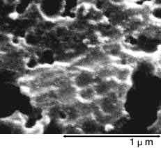
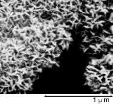
Below photographs show a magnified view of the oxide layer produced through anode oxidation.
| Low-voltage forming foil | High-voltage forming foil |
| 
| 
|
| Photograph of surface | Photograph of surface |
2011-1-19 18:58:59
views
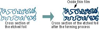
[2]-1 Surface Roughing (Etching)
The raw foil for the anode uses a high-purity aluminum foil (a minimum purity level of 99.99%) that is normally 50 to 100 m thick. The cathode foil material uses an aluminum foil that is at least 99% pure and about 15 to 60 m thick. Because the capacitance is proportional to the surface area of the electrodes, the effective surface area is increased by roughening (etching) the surface of the aluminum foil before growing the dielectric film. Generally, this surface roughening is referred to as "etching."
There are two typical etching processes. The first option submerges the aluminum foil in hydrochloric acid (physical etching). A secondary option is electrolysis where the aluminum as the anode is placed in an aqueous hydrochloric acid solution (electrochemical etching). In electrochemical etching, the etching profile will vary depending on factors such as the waveform of the electrical current, the composition of the solution, and the temperature. The etching method can be determined by the desired capacitor performance. Generally, it is possible to achieve etching multipliers (the ratio between the surface area of the smooth foil and the effective surface area of the etched foil) approximately between 3 and 120.
The foil is then rinsed thoroughly with water. Any residual chlorine ions on the foil's surface after etching can corrode the foil and damage the capacitor. After etching, the foil's surface can be categorized broadly as shown below by the selected voltage at which the capacitor functions properly. See the magnified view of the surface in below photograph.
| | Foil Surface
(3500x Magnification) | Cross-section of Capacitor
(350x Magnification) |
Types of
Etched Foils | Low-voltage foil |  |  |
| High-voltage foil |  |  |
2011-1-18 18:53:4
views
[2] Aluminum Electrolytic Capacitors
The anode in the aluminum electrolytic capacitor is made from a high-purity aluminum foil with an aluminum oxide thin film dielectric on its surface. The capacitor is structured using an electrolytic paper containing an electrolytic solution and an aluminum electrode foil for contacting the cathode.
The thickness of the anode oxide thin film is the distance between the electrodes (t) show at below in the section on how capacitors function. The thickness of the anode oxide thin film in an aluminum electrolytic capacitor is selected by the required withstand voltage. Large amounts of charge can be stored in a small capacitor because the value for t can be made extremely small. This occurs because the value for the electrode surface area (S) can be increased by roughening the surface, and because the dielectric constant ( ) is large.

2011-1-17 23:56:28
views
[1] How Capacitors Work
Below picture shows the basic concepts of how capacitors function.
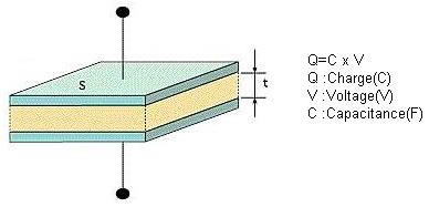
A dielectric material is layered between two metal electrodes, and an electrical charge proportional to the voltage is stored in the capacitor when a voltage is applied across the electrodes.
"C" is the capacitance of the capacitor. The capacitance is calculated using the equation shown below as a function of the surface area of the electrodes (S), the distance between the electrodes (t), and the dielectric constant of the dielectric ( ).
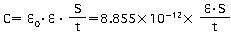
In the formula above, 0 represents the permittivity of free space (8.85 x 10⁻¹²F/m)
A larger capacitance can be obtained by either increasing the dielectric constant, increasing the electrode surface area (S), or by decreasing the distance between the electrodes(t).
The dielectric constant of an aluminum oxide layer averages between 7 and 8. The most frequent dielectric constants of dielectrics used in capacitors are listed in below table.
The effective surface area of aluminum electrolytic capacitors can be increased by as much as 120 times. By roughening the surface of the high-purity aluminum foil, the process makes it possible to produce capacitances far larger than those of other types of capacitors.
| Dielectric Material | Dielectric Constant | Dielectric Material | Dielectric Constant |
| Aluminum oxide thin film | 7 - 8 | Porcelain (ceramic) | 10 - 120 |
| Mylar | 3.2 | Polyethylene | 2.5 |
| Mica | 6 - 8 | Tantalum oxide film | 10 - 20 |
Please note that capacitors are typically described in terms of the primary dielectric material. A few examples are "aluminum electrolytic capacitor" or "tantalum capacitor."
2011-1-14 23:9:19
views
Aluminum electrolytic capacitors are widely used in the circuits of electronic devices. Electrolytic capacitors are attached to printed circuit boards, either individually or in batteries. A common type of aluminum electrolytic capacitor comprises a capacitor element formed by winding an anode foil and a cathode foil through a separator, an electrolyte solution for driving impregnating this capacitor element, a metal case accommodating the capacitor element, and an elastic sealing member sealing the metal case.
Follow jb, you can find the favorite Aluminum Electrolytic Capacitors.Below link you can go to view the favorite Aluminum Electrolytic Capacitors in jb website.
http://www.jbcapacitors.com/Aluminum-Electrolytic-Capacitors/
2011-1-5 22:30:25
views
As already mentioned at previous blog, never go below the voltage rating of the original part. Standards in voltage ratings have changed over the years, so you may not be able to find an exact replacement for the 250V capacitor you want to replace. Instead use 270V or even more. The only adverse effects of using a too high rating is price and, maybe, physical size; small problems compared to the risk of a capacitor impersonating a large firecracker inside your equipment!
Same is true of capacitance values: Standards have changed, and instead of old values like 15MF, 32MF, 50MF, etc, you will find 16, 33, 67, and such. The capacitance values of electrolytic capacitors are normally not very critical to the circuitry function, especially not in filters. A good rule of thumb is to go for the range between -20% to +100% of the original value, of course choosing a value as close as you can get.
There is a caveat here: If those capacitors have already been changed once, the values you look at may already deviate from the original values. If a 260V 40MF capacitor has sometime along the route been replaced with a 450V 67MF, you could be heading for problems; a 650V 100MF replacement will probably work, but we are getting out of bounds (oversize filter caps put extra strain on rectifier tubes, not to mention the price). So it would be nice to make a rough calculation to see if the value we are aiming for is reasonable.
