2011-6-1 15:32:36
views
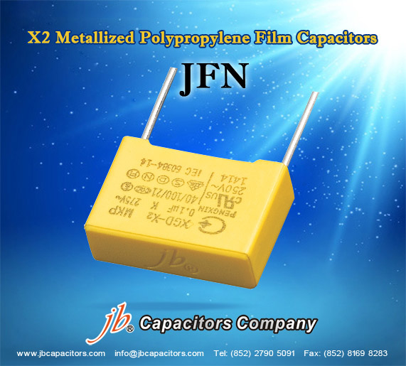
Description :
1. High frequency operation.
2. High du / dt.
3. High insulation resistance.
4. Flame retardant epoxy resin (UL 94V-0).
Specification :
1. Operating temperature: -40℃~+100℃.
2. Capacitance range: 0.0022μF~1μF.
3. Capacitance tolerance: ±10% (K).
4. Rated voltage: 300V, 280V, 275V. 250V.AC
5. Dissipation factor: 0.08% max at 1KHz 20℃ 0.3% max at 10KHz 20℃.
6. Insulation resistance: 1.R≥30,000MΩ (C≤0.33μF) 1.R≥10,000MΩ (C>0.33μF)
2011-5-13 17:49:11
views
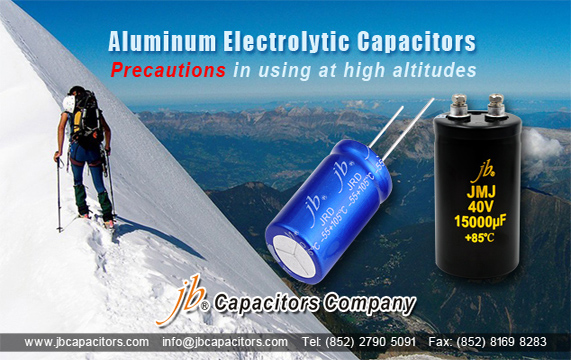
Here are precautions in using aluminum electrolytic capacitors at high altitudes, such as in
mountainous regions and in aircrafts.
As the altitude rises, the air pressure decreases. Therefore, if the capacitor is used at high altitudes, the atmospheric pressure becomes lower than the internal pressure of the capacitor. Due to the
construction of the aluminum electrolytic capacitor, there is no concern in using them at altitudes lower than about 10,000 (m).
2011-5-6 13:37:20
views
For reflow, use thermal conduction systems such as infrared radiation (IR) or hot blast. Vapor heat
transfer systems (VPS) are not recommended.
Observe proper soldering conditions (temperature, time, etc.).
Do not exceed the specified limits.
Temperature measuring method: Measure temperature in assuming quantitative production, by sticking the thermo-couple to the capacitor upper part with epoxy adhesives.
Consult us for additional reflow restrictions.

2011-5-2 22:48:36
views
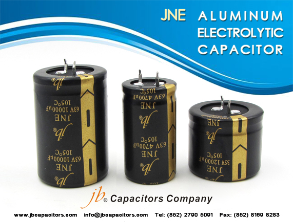
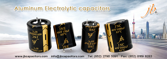
jb Aluminum Electrolytic Capacitor - JNE
Features
- Load life of 2000 hours at 105°C
- High ripple current
- Smaller size
- PCB Mounting
Construction
- Charge/discharge-proof, polar
- Aluminum case, fully insulated with PVC
- Version with PET insulation available
- Version with additional PET insulation cap on terminal side
- available for insulating the capacitor from the PCB
- Snap-in solder pins to hold component in place on PC-board
- Minus pole marking on case surface
- Minus pole not insulated from case
- Overload protection by safety vent on the base
2011-4-29 10:17:53
views
In theory, capacitors can be coupled both in series and parallel. If you need a 100MF cap and have two at 50MF, you can connect them in parallel, and that will give you 100MF (and same voltage rating as each). If you couple them in series, you get half the capacitance, and double voltage rating. But coupling electrolytic capacitors in series to get higher voltage rating must generally be discouraged. For this to work, you must be sure that the two (or more) caps share the voltage load properly; a resistor network can augment this, but if leakage currents are markedly different or the capacitors age differently, you are looking at a potential disaster, so do this only as a last resort, if at all.
2011-4-19 11:55:32
views
Aluminum Electrolytic Capacitor are connected in series, back-to-back with the positive terminals or the negative terminals connected, the resulting single capacitor is a non-polar capacitor with half the capacitance. The two capacitors rectify the applied voltage and act as if they had been bypassed by diodes. When voltage is applied, the correct-polarity capacitor gets the full voltage. In non-polar aluminum electrolytic capacitors and motor-start aluminum electrolytic capacitors a second anode foil substitutes for the cathode foil to achieve a non-polar capacitor in a single case.
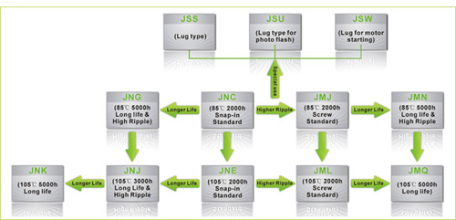
jb Capacitors markets Aluminum Electrolytic Capacitors, including JNC, JNE ,JNG ,JNJ , JNK , JMJ ……The following Picture shows our Aluminum Electrolytic Capacitors. For the detailed information ,We introduced in our website www.jbcapacitors.com .If necessary, you can contact our sales directly. I am sure you can get your satisfaction.
2011-4-13 12:25:15
views
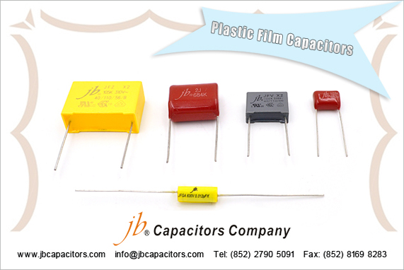
Film Capacitors are Non polarized, and may be used in AC or DC circuits.
Typical values range form 1000pF to 1uF for Polyerster Film, and 0.01uF to 18uF for Metallized Film capacitors. Standard Film Capacitor values change in multiples of 10, 12, 15, 18, 22, 27, 33, 39, 47, 56, 68, 82.
Normal Temperature Coefficient [TC] for Film Capacitors is +7%.
- Mylar: has a wide temperature change of 20% over -55 to +125°C. Moisture absorption is half that of paper.
Mylar is the same as polyester. The term Mylar is a trade name. - Polycarbonate: Out performs Mylar in all areas. Low Power factor, works best with AC. Polycarbonate has a low temperature drift (graph below), dissipation factor, and dielectric absorption. Use polyphenylene sulfide as a possible replacement.
- Polyester: Replaces paper for many applications, and smaller in size. Polyester does not have the moisture problem that paper does, but does have a worse tolerance, at 20% ~ over -55 to +125°C. May also be called PETE, or PETP. The Polyester Dielectric has an Absorption of around 0.20%.
- Polypropylene: It has negative temperature coefficient.
- Polysulfone: Has a very high operating temperature of +170°C.
- Polystyrene: Will only work to +65°C. It has a flat to negative temperature coefficient.
- Teflon: Has a very high operating temperature of +170°C.
2011-3-11 12:1:55
views
A colour code was used on polyester capacitors for many years. It is now obsolete, but of course there are many still around. The colours should be read like the resistor code, the top three colour bands giving the value in pF. Ignore the 4th band (tolerance) and 5th band (voltage rating).
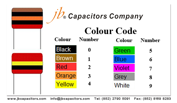
For example:brown, black, orange means 10000pF = 10nF = 0.01µF.
Note that there are no gaps between the colour bands, so 2 identical bands actually appear as a wide band.
For example:wide red, yellow means 220nF = 0.22µF.
2011-2-26 16:40:12
views
To use this table, just read across. For example, 1uF is same 1,000nF or 1,000,000pF.
| uF/ MFD | nF | pF/ MMFD | | uF/ MFD | nF | pF/ MMFD |
| 1uF / MFD | 1000nF | 1000000pF(MMFD) | | 0.001uF / MFD | 1nF | 1000pF(MMFD) |
| 0.82uF / MFD | 820nF | 820000pF (MMFD) | | 0.00082uF / MFD | 0.82nF | 820pF (MMFD) |
| 0.8uF / MFD | 800nF | 800000pF (MMFD) | | 0.0008uF / MFD | 0.8nF | 800pF (MMFD) |
| 0.7uF / MFD | 700nF | 700000pF (MMFD) | | 0.0007uF / MFD | 0.7nF | 700pF (MMFD) |
| 0.68uF / MFD | 680nF | 680000pF (MMFD) | | 0.00068uF / MFD | 0.68nF | 680pF (MMFD) |
| 0.6uF / MFD | 600nF | 600000pF (MMFD) | | 0.0006uF / MFD | 0.6nF | 600pF (MMFD) |
| 0.56uF / MFD | 560nF | 560000pF (MMFD) | | 0.00056uF / MFD | 0.56nF | 560pF (MMFD) |
| 0.5uF / MFD | 500nF | 500000pF (MMFD) | | 0.0005uF / MFD | 0.5nF | 500pF (MMFD) |
| 0.47uF / MFD | 470nF | 470000pF (MMFD) | | 0.00047uF / MFD | 0.47nF | 470pF (MMFD) |
| 0.4uF / MFD | 400nF | 400000pF (MMFD) | | 0.0004uF / MFD | 0.4nF | 400pF (MMFD) |
| 0.39uF / MFD | 390nF | 390000pF (MMFD) | | 0.00039uF / MFD | 0.39nF | 390pF (MMFD) |
| 0.33uF / MFD | 330nF | 330000pF (MMFD) | | 0.00033uF / MFD | 0.33nF | 330pF (MMFD) |
| 0.3uF / MFD | 300nF | 300000pF (MMFD) | | 0.0003uF / MFD | 0.3nF | 300pF (MMFD) |
| 0.27uF / MFD | 270nF | 270000pF (MMFD) | | 0.00027uF / MFD | 0.27nF | 270pF (MMFD) |
| 0.25uF / MFD | 250nF | 250000pF (MMFD) | | 0.00025uF / MFD | 0.25nF | 250pF (MMFD) |
| 0.22uF / MFD | 220nF | 220000pF (MMFD) | | 0.00022uF / MFD | 0.22nF | 220pF (MMFD) |
| 0.2uF / MFD | 200nF | 200000pF (MMFD) | | 0.0002uF / MFD | 0.2nF | 200pF (MMFD) |
| 0.18uF / MFD | 180nF | 180000pF (MMFD) | | 0.00018uF / MFD | 0.18nF | 180pF (MMFD) |
| 0.15uF / MFD | 150nF | 150000pF (MMFD) | | 0.00015uF / MFD | 0.15nF | 150pF (MMFD) |
| 0.12uF / MFD | 120nF | 120000pF (MMFD) | | 0.00012uF / MFD | 0.12nF | 120pF (MMFD) |
| 0.1uF / MFD | 100nF | 100000pF (MMFD) | | 0.0001uF / MFD | 0.1nF | 100pF (MMFD) |
| 0.082uF / MFD | 82nF | 82000pF (MMFD) | | 0.000082uF / MFD | 0.082nF | 82pF (MMFD) |
| 0.08uF / MFD | 80nF | 80000pF (MMFD) | | 0.00008uF / MFD | 0.08nF | 80pF (MMFD) |
| 0.07uF / MFD | 70nF | 70000pF (MMFD) | | 0.00007uF / MFD | 0.07nF | 70pF (MMFD) |
| 0.068uF / MFD | 68nF | 68000pF (MMFD) | | 0.000068uF / MFD | 0.068nF | 68pF (MMFD) |
| 0.06uF / MFD | 60nF | 60000pF (MMFD) | | 0.00006uF / MFD | 0.06nF | 60pF (MMFD) |
| 0.056uF / MFD | 56nF | 56000pF (MMFD) | | 0.000056uF / MFD | 0.056nF | 56pF (MMFD) |
| 0.05uF / MFD | 50nF | 50000pF (MMFD) | | 0.00005uF / MFD | 0.05nF | 50pF (MMFD) |
| 0.047uF / MFD | 47nF | 47000pF (MMFD) | | 0.000047uF / MFD | 0.047nF | 47pF (MMFD) |
| 0.04uF / MFD | 40nF | 40000pF (MMFD) | | 0.00004uF / MFD | 0.04nF | 40pF (MMFD) |
| 0.039uF / MFD | 39nF | 39000pF (MMFD) | | 0.000039uF / MFD | 0.039nF | 39pF (MMFD) |
| 0.033uF / MFD | 33nF | 33000pF (MMFD) | | 0.000033uF / MFD | 0.033nF | 33pF (MMFD) |
| 0.03uF / MFD | 30nF | 30000pF (MMFD) | | 0.00003uF / MFD | 0.03nF | 30pF (MMFD) |
| 0.027uF / MFD | 27nF | 27000pF (MMFD) | | 0.000027uF / MFD | 0.027nF | 27pF (MMFD) |
| 0.025uF / MFD | 25nF | 25000pF (MMFD) | | 0.000025uF / MFD | 0.025nF | 25pF (MMFD) |
| 0.022uF / MFD | 22nF | 22000pF (MMFD) | | 0.000022uF / MFD | 0.022nF | 22pF (MMFD) |
| 0.02uF / MFD | 20nF | 20000pF (MMFD) | | 0.00002uF / MFD | 0.02nF | 20pF (MMFD) |
| 0.018uF / MFD | 18nF | 18000pF (MMFD) | | 0.000018uF / MFD | 0.018nF | 18pF (MMFD) |
| 0.015uF / MFD | 15nF | 15000pF (MMFD) | | 0.000015uF / MFD | 0.015nF | 15pF (MMFD) |
| 0.012uF / MFD | 12nF | 12000pF (MMFD) | | 0.000012uF / MFD | 0.012nF | 12pF (MMFD) |
| 0.01uF / MFD | 10nF | 10000pF (MMFD) | | 0.00001uF / MFD | 0.01nF | 10pF (MMFD) |
| 0.0082uF / MFD | 8.2nF | 8200pF (MMFD) | | 0.0000082uF / MFD | 0.0082nF | 8.2pF (MMFD) |
| 0.008uF / MFD | 8nF | 8000pF (MMFD) | | 0.000008uF / MFD | 0.008nF | 8pF (MMFD) |
| 0.007uF / MFD | 7nF | 7000pF (MMFD) | | 0.000007uF / MFD | 0.007nF | 7pF (MMFD) |
| 0.0068uF / MFD | 6.8nF | 6800pF (MMFD) | | 0.0000068uF / MFD | 0.0068nF | 6.8pF (MMFD) |
| 0.006uF / MFD | 6nF | 6000pF (MMFD) | | 0.000006uF / MFD | 0.006nF | 6pF (MMFD) |
| 0.0056uF / MFD | 5.6nF | 5600pF (MMFD) | | 0.0000056uF / MFD | 0.0056nF | 5.6pF (MMFD) |
| 0.005uF / MFD | 5nF | 5000pF (MMFD) | | 0.000005uF / MFD | 0.005nF | 5pF (MMFD) |
| 0.0047uF / MFD | 4.7nF | 4700pF (MMFD) | | 0.0000047uF / MFD | 0.0047nF | 4.7pF (MMFD) |
| 0.004uF / MFD | 4nF | 4000pF (MMFD) | | 0.000004uF / MFD | 0.004nF | 4pF (MMFD) |
| 0.0039uF / MFD | 3.9nF | 3900pF (MMFD) | | 0.0000039uF / MFD | 0.0039nF | 3.9pF (MMFD) |
| 0.0033uF / MFD | 3.3nF | 3300pF (MMFD) | | 0.0000033uF / MFD | 0.0033nF | 3.3pF (MMFD) |
| 0.003uF / MFD | 3nF | 3000pF (MMFD) | | 0.000003uF / MFD | 0.003nF | 3pF (MMFD) |
| 0.0027uF / MFD | 2.7nF | 2700pF (MMFD) | | 0.0000027uF / MFD | 0.0027nF | 2.7pF (MMFD) |
| 0.0025uF / MFD | 2.5nF | 2500pF (MMFD) | | 0.0000025uF / MFD | 0.0025nF | 2.5pF (MMFD) |
| 0.0022uF / MFD | 2.2nF | 2200pF (MMFD) | | 0.0000022uF / MFD | 0.0022nF | 2.2pF (MMFD) |
| 0.002uF / MFD | 2nF | 2000pF (MMFD) | | 0.000002uF / MFD | 0.002nF | 2pF (MMFD) |
| 0.0018uF / MFD | 1.8nF | 1800pF (MMFD) | | 0.0000018uF / MFD | 0.0018nF | 1.8pF (MMFD) |
| 0.0015uF / MFD | 1.5nF | 1500pF (MMFD) | | 0.0000015uF / MFD | 0.0015nF | 1.5pF (MMFD) |
| 0.0012uF / MFD | 1.2nF | 1200pF (MMFD) | | 0.0000012uF / MFD | 0.0012nF | 1.2pF (MMFD) |
| 0.001uF / MFD | 1nF | 1000pF (MMFD) | …… | 0.000001uF / MFD | 0.001nF | 1pF (MMFD) |
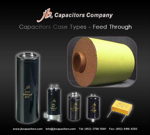
2011-1-29 21:27:56
views
Round Feed Through capacitors, in a skin tight plastic wrap with solderable ends (Style Q). The hole in the center of the capacitor is either a Teflon Tube, Paper Tube or Phenolic Tube ranging in sizes from just a wire to a large threaded stud to fit through. The majority of Feed Throughs are custom made to exact customer requirements. They are very popular in filter applications.