2011-5-11 22:51:53
views
A run capacitor is a particular type of capacitor. A run capacitor uses the charge stored in the dielectric in order to boost the electrical current providing power to an electric motor. This type of capacitor is created to maintain a charge during constant use of the motor. These capacitors are often found in devices, such as heaters, that are continuously running.
One variety of run capacitor is often used in air conditioners. This type of run capacitor is called a dual run capacitor, and uses two run capacitors for two different functions. In an air conditioner, for example, one run capacitor is used to boost the fan motor, and another is used to boost the compressor motor.
Run capacitors typically are classified at 370 or 440 volts. It is necessary to ensure that the correct rating of run capacitor is installed in an engine. If a run capacitor with an incorrect voltage rating is installed in a motor that requires a capacitor for second-phase energy, it will throw off the magnetic field. An uneven magnetic field will cause the rotor to slow in the uneven spots, which increases energy noise, as well as power consumption, and can also cause performance problems and overheating issues.
2011-4-29 10:17:53
views
In theory, capacitors can be coupled both in series and parallel. If you need a 100MF cap and have two at 50MF, you can connect them in parallel, and that will give you 100MF (and same voltage rating as each). If you couple them in series, you get half the capacitance, and double voltage rating. But coupling electrolytic capacitors in series to get higher voltage rating must generally be discouraged. For this to work, you must be sure that the two (or more) caps share the voltage load properly; a resistor network can augment this, but if leakage currents are markedly different or the capacitors age differently, you are looking at a potential disaster, so do this only as a last resort, if at all.
2011-4-15 15:59:12
views
An Integrated Circuit [IC] is normally decoupled using one bypass capacitor from 0.01uf to 0.1uf.Using the graph below, the 0.1uf response would result in the first dip at f1 followed by the dotted single line.
Placing a 0.01uf capacitor in parallel with the first cap also provides the second dip at f2 increasing the frequency response of the pair of caps.
The graphic above shows the benefit of placing two different value capacitors in parallel.
The impedance is reduced across a band of frequencies, adding the two nulls.
The first null is developed from the larger value capacitor, and the second null from the smaller value capacitor.
Placing a large value Tantalum capacitor next to a smaller value ceramic will cover a wide range of frequencies.
Placing two ceramic capacitors, a decade apart in value, in parallel will have the same effect but over a different frequency range.
2011-4-8 23:22:39
views
In many applications capacitors need not be specified to tight tolerance (they often need only to exceed a certain value); this is particularly true for electrolytic capacitors, which are often used for filtering and bypassing. Consequently capacitors, particularly electrolytics, often have a tolerance range of ±20% and need to be available only within E6 (or E3) series values.
| Series | Values |
| E3 | 1.0 | | | | 2.2 | | | | 4.7 | | | |
| E6 | 1.0 | | 1.5 | | 2.2 | | 3.3 | | 4.7 | | 6.8 | |
| E12 | 1.0 | 1.2 | 1.5 | 1.8 | 2.2 | 2.7 | 3.3 | 3.9 | 4.7 | 5.6 | 6.8 | 8.2 |
Other types of capacitors, e.g. ceramic, can be manufactured to tighter tolerances and are available in E12 or closer-spaced values (e.g. 47 pF, 56 pF, 68 pF).
With the introduction of S.I. submultiples of micro, nano, and pico, it became customary to specify capacitors with a number between 1 and 999 followed by farad, microfarad, nanofarad, or picofarad. While supercapacitors of up to 5,000 farads are produced, it is not usual to use kilofarad or millifarad.
2011-4-2 10:32:15
views
Capacitor plague (also known as bad capacitors) is an ongoing problem with premature failure of large numbers of electrolytic capacitors of certain brands. Capacitors are used in various electronics equipment, particularly motherboards, video cards, compact fluorescent lamp ballasts, LCD monitors, and power supplies of personal computers. The first flawed capacitors were seen in 1999, but most of the affected capacitors were made in the early to mid 2000s. News of the failures (usually after a few years of use) forced most manufacturers to repair the defects and stop using the capacitors, but some bad capacitors were still being sold or used in equipment as of early 2007[update], and faults are still being reported as of 2011[update].Reference computer user reports on badcaps.net.
A serious quality control problem is that the issue only manifests after use over a period of time; poor quality electrolytic capacitors have the same measurable parameters as good ones when new. Only extensive accelerated life testing with high ripple currents and high operating temperatures can identify inferior components. After some normal use the bad capacitors fail predictably far sooner than normal end-of-life; most electronic components do not systematically fail in this way.
2011-3-31 11:41:44
views
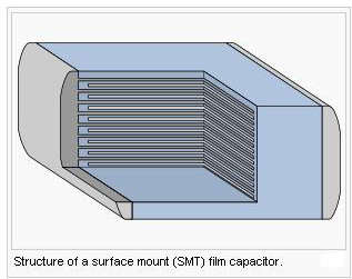
Capacitors have thin conducting plates (usually made of metal), separated by a layer of dielectric, then stacked or rolled to form a compact device.
Many types of capacitors are available commercially, with capacitance ranging from the picofarad, microfarad range to more than a farad, and voltage ratings up to hundreds of kilovolts. In general, the higher the capacitance and voltage rating, the larger the physical size of the capacitor and the higher the cost. Tolerances in capacitance value for discrete capacitors are usually specified as a percentage of the nominal value. Tolerances ranging from 50% (electrolytic types) to less than 1% are commonly available.
Another figure of merit for capacitors is stability with respect to time and temperature, sometimes called drift. Variable capacitors are generally less stable than fixed types.
2011-3-30 20:20:37
views
The breakdown voltage of the dielectric limits the power density of capacitors. For a particular dielectric, the breakdown voltage is proportional to the thickness of the dielectric.
If a manufacturer makes a new capacitor with the same dielectric as some old capacitor, but with half the thickness of the dielectric, the new capacitor has half the breakdown voltage of the old capacitor.
Because the plates are closer together, the manufacturer can put twice the parallel-plate area inside the new capacitor and still fit it in the same volume (capacitor size) as the old capacitor. Since the capacitance of a parallel-plate capacitor is given by:

this new capacitor has 4 times the capacitance as the old capacitor.
Since the energy stored in a capacitor is given by:
this new capacitor has the same maximum energy density as the old capacitor.
2011-3-28 19:44:32
views
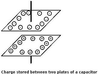
Capacitance is the ability to store electric charge. In its simplest form a capacitor consists of two parallel plates or electrodes that are separated from each other by an insulating dielectric. It is found that when a battery or any other voltage source is connected to the two plates as shown a current flows for a short time as it charges up. It is found that one plate of the capacitor receives an excess of electrons, while the other has too few. In this way the capacitor plate or electrode with the excess of electrons becomes negatively charged, while the capacitor electrode becomes positively charged.
2011-3-26 12:28:48
views
When using a capacitor, you must pay attention to the maximum voltage which can be used. This is the "breakdown voltage." The breakdown voltage depends on the kind of capacitor being used. You must be especially careful with electrolytic capacitors because the breakdown voltage is comparatively low. The breakdown voltage of electrolytic capacitors is displayed as Working Voltage.
The breakdown voltage is the voltage that when exceeded will cause the dielectric (insulator) inside the capacitor to break down and conduct. When this happens, the failure can be catastrophic.
2011-3-23 12:17:16
views
In theory, the dielectric can be any nonconductive substance. However, for practical applications, specific materials are used that best suit the capacitor's function. Mica, ceramic, cellulose, porcelain, Mylar, Teflon and even air are some of the nonconductive materials used. The dielectric dictates what kind of capacitor it is and for what it is best suited. Depending on the size and type of dielectric, some capacitors are better for high frequency uses, while some are better for high voltage applications. Capacitors can be manufactured to serve any purpose, from the smallest plastic capacitor in your calculator, to an ultra capacitor that can power a commuter bus. NASA uses glass capacitors to help wake up the space shuttle's circuitry and help deploy space probes. Here are some of the various types of capacitors and how they are used.
Air - Often used in radio tuning circuits
Mylar - Most commonly used for timer circuits like clocks, alarms and counters
Glass - Good for high voltage applications
Ceramic - Used for high frequency purposes like antennas, X-ray and MRI machines
Super capacitor - Powers electric and hybrid cars
