2012-7-20 9:41:30
views
jb Large Can type Aluminum Electrolytic Capacitors---Cross Reference Nichicon, Chemi-con, Panasonic, Samwha...
jb capacitors company produce the top high quality for large can type aluminum electrolytic capacitors in China. Mainly are Screw terminals, snap-in pins, and lug terminals.
Below are some cross reference for our aluminum electrolytic capacitors screw type & Snap-in type
| Surface Mount/SMD | Load Life | jb capacitors | Rubycon | Nippon | Nichicon | Panasonic |
| General Purpose | Chemi-Con |
| | 2000h at 85C | JCS | SEV | MVA | UWX | EEE-X(A)S |
| | (1000h~2000h) at 105C | JCK | SKV | MVE | UWT | EEEHA |
| Snap in Terminals | Load Life | jb capacitors | Epcos | Nippon | Nichicon | Panasonic |
| Chemi-Con |
| 2000h at 85C | JNC | B41231 | SMQ | LS | TS-UQ |
| B43510/B43520 | SMH | LG | T-UP |
| 3000h at 85C | B43511/B43521 | SMM | | |
| 2000h at 105C | JNE | B41252 | KMQ, KMH | GG | TS-MD |
| B43504 | KMT | GL | TS-HC |
| B43515/B43525 | KMR | AK,AQ | |
| 5000h at 85C | JNG | B43501 | | | |
| B43540 | | | |
| 3000h at 105C | JNJ | | KMS | GU | TS-ED |
| | KMM | GN | TS-EE |
| | KMV | GW | TS-HA/HB |
| 5000h at 105c | JNK | B41505 | LXS | GY | |
| B43505 | LXG | GX | |
| | LXQ | | |
| Screw Terminals | Load life | jb capacitors | Epcos | Nippon | Nichicon | Hitachi |
| Chemi-Con |
| 2000h at 85C | JMJ | B41456,B41458 | ESME | LNY | HCGW2 |
| B43456,B43458 | ERWQ | | HCGWA |
| B43564,B43584 | ERWE | | HCGF5/6A |
| B43455,B43457 | | | HCG7A |
| 2000h at 105C | JML | B43740,B43760 | EKMH | LNT | HCGHA |
| B41560,B41580 | | | |
| B43750,B43770 | | | |
| 5000h at 85C | JMN | | ERWG | LNR | FXW |
| | ERWF | LNK | FXR3 ,FXR |
| | ERWY, RWV | LNC | GXR3 |
| | | | FXA,FX2,FX3 |
| 5000h at 105C | JMQ | | ELXA | LNT | GXR |
| | ELXR | | GXA |
| | | | GX2, GX3 |
| Surface Mount/SMD | Load Life | jb capacitors | Samwha | Sanyo | Yageo | DAEWOO |
| General Purpose |
| | 2000h at 85C | JCS | SC | CE-BS | CA | CS |
| | (1000h~2000h) at 105C | JCK | RC | CE-FS | CB | CU |
| Snap in Terminals | Load Life | jb capacitors | Samwha | Kendeil | Yageo | DAEWOO |
| 2000h at 85C | JNC | HC | K26 | LH | FHS |
| AM | | | FHX |
| 3000h at 85C | | | | FHT |
| 2000h at 105C | JNE | HE | K25 | LG | FUH |
| | | | |
| | | | |
| 5000h at 85C | JNG | | K06 | | |
| | K16 | | |
| 3000h at 105C | JNJ | HE | | LV | FUT |
| HK | | | |
| | | | |
| 5000h at 105c | JNK | HL | K05 | LC | FUL |
| | K15 | | |
| | | | |
| Screw Terminals | Load life | jb capacitors | Samwha | Kendeil | Yageo | DAEWOO |
| 2000h at 85C | JMJ | GT | K01 | NP | PSA |
| GK | K07 | NG | |
| | K11 | | |
| | K21 | | |
| 2000h at 105C | JML | CU | K02 | NM | PUH |
| | K22 | | |
| | | | |
| 5000h at 85C | JMN | GF | K04 | NF | |
| GH | | | |
| GN | | | |
| | | | |
| 5000h at 105C | JMQ | EV | | NH | |
| | | | |
| | | | |
2012-7-18 9:27:3
views
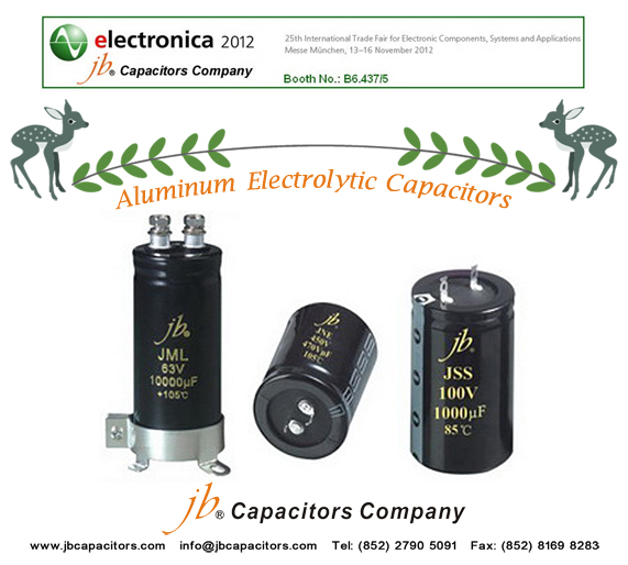
jb capacitors company produce the top high quality for large can type aluminum electrolytic capacitors in China.
Mainly are Screw terminals, snap-in pins, and lug terminals, below pictures for your kindly information.
contactinfo@jbcapacitors.com for details.
2012-7-3 11:29:26
views
Keywords: Aluminum Electrolytic Capacitors, electrolytic capacitors, kondensatory, Large Can E-cap.
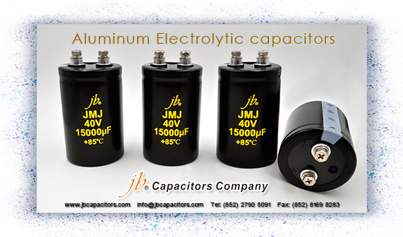
jb Capacitors manufactures and markets Screw Aluminum Electrolytic Capacitor, with wide temperature range and extra long life 5000 hours, and with reasonable prices based on high quality. Please refer to below item series of Aluminum Electrolytic Capacitors,
Screw Aluminum Electrolytic Capacitors have four items series as followed:
1. JMJ - 2000H at 85°C, Miniaturized, Screw Aluminum Electrolytic Capacitor
2. JML - 2000H at 105°C Screw Aluminum Electrolytic Capacitor
3. JMN - 5000H at 85°C Screw Aluminum Electrolytic Capacitor
4. JMQ - 5000H at 105°C Screw Aluminum Electrolytic Capacitor
Application:
Widely used in General-purpose Inverter, Hi-ripple circuit of electric vehicle, electric train,
Power Supplies, Communication powers, Computer, UPS, Energy Discharge, i.e. Welding Machines.
welcome send inquiry to info@jbcapacitors.com

2012-3-19 10:59:33
views
SMD Electrolytic Capacitors Offer (jb capacitors)
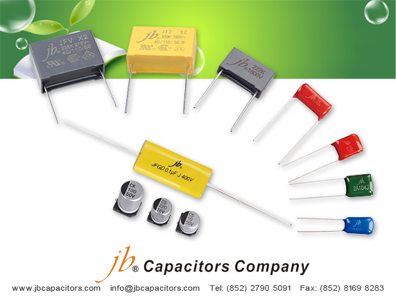
We produce 22 series of MKT, MKP film capacitors. Our JFV X2 MKP Safety Capacitor and JFD Box type metallized polyester capacitor
are used on Bosch and Philips application. We produce high quality capacitors.
Besides, we wouldd like to recommend you our strong series SMD Electrolytic Capacitor, please check below our description and simple cross guide.
Just send me your inquiry please, I will offer you our the most attractive prices.
JCS-- SMD aluminum electrolytic capacitors 85'C
JCK-- SMD aluminum electrolytic capacitors 105'C

Contact : Ms. May Wong---Sales Manager by email may@jbcapacitors.hk
2011-10-10 1:4:11
views
Keywords: Polarised, DC power supply circuit, large capacitance.
Electrolytic Capacitors are generally used when very large capacitance values are required. Here instead of using a very thin metallic film layer for one of the electrodes, a semi-liquid electrolyte solution in the form of a jelly or paste is used which serves as the second electrode (usually the cathode). The dielectric is a very thin layer of oxide which is grown electro-chemically in production with the thickness of the film being less than ten microns. This insulating layer is so thin that it is possible to make capacitors with a large value of capacitance for a small physical size as the distance between the plates, D is very small.
The majority of electrolytic types of capacitors are Polarised, that is the DC voltage applied to the capacitor terminals must be of the correct polarity, i.e. positive to the positive terminal and negative to the negative terminal as an incorrect polarisation will break down the insulating oxide layer and permanent damage may result. All polarised electrolytic capacitors have their polarity clearly marked with a negative sign to indicate the negative terminal and this polarity must be followed.
Electrolytic Capacitors are generally used in DC power supply circuits due to their large capacitances and small size to help reduce the ripple voltage or for coupling and decoupling applications. One main disadvantage of electrolytic capacitors is their relatively low voltage rating and due to the polarisation of electrolytic capacitors, it follows then that they must not be used on AC supplies. Electrolytic's generally come in two basic forms: Aluminum Electrolytic Capacitors and Tantalum Electrolytic Capacitors.
Structure

2011-10-7 23:40:15
views
Sie sind auf der Suche nach einem exzelentem und zuverlässigen ondensatorhersteller in China?
Dann können wir von jb Capacitors helfen!
Mein Name ist Chaney und ich betreue unsere Kunden in Deutschland.
Unser Lieferprogramm:
JFA-Mylar Polyester Film Kondensator (CL-11)
JFB-Metall Polyester Film Kondensator (CL-21)
JFE-Mini Metall Polyester Film Kondensator (CL-21X)
JFD-Box Type Metall Polyester Film Kondensator (CL-23)
JFG-Axial Metall Polyester & Polypropylene Film Kondensator
JFL-Metall Polypropylen Film Kondensator (CBB-21)
JFV-X2 Metall Polypropylen Film Kondensator, with safety approvals
JFP-High Voltage Metall Polypropylen Film Kondensator (CBB81)
JCS-SMD Typ Aluminum Electrolyt Kondensator, 85C, 2000H
JCK-SMD Typ Aluminum Electrolyt Kondensator, 105C, 1000H
Wir garantieren:
Qualität, ISO9001 : 2000 Zertifizierung seit 1980 (!)
Erfahrung im Kondensatorbau seit über 30 Jahren
Pünktliche Lieferung innerhalb von 5 bis 7 Wochen
Beste Verpackung nach deutschen Qualitätsansprüchen
Beste Technologie aus Taiwan und Hongkong
Internationale Safety – Standards cUL, CSA, VDE, GS etc
Unschlagbares Preis/ Leistungsverhältnis, Kein Zwischenhandel
Ich freue mich auf Ihre Anfrage - Sie erhalten umgehend unser Angebot.
Für weitere Informationen stehe ich Ihnen jederzeit gerne zur Verfügung.
Sie erreichen mich persönlich zu Ihren gewohnten deutschen Geschäftszeiten.
Mit herzlichen Grüßen nach Deutschland
Chaney ( info@jbcapacitors.com)
2011-9-30 23:20:47
views
Keywords: Polarised, DC power supply circuit, large capacitance.
Electrolytic Capacitors are generally used when very large capacitance values are required. Here instead of using a very thin metallic film layer for one of the electrodes, a semi-liquid electrolyte solution in the form of a jelly or paste is used which serves as the second electrode (usually the cathode). The dielectric is a very thin layer of oxide which is grown electro-chemically in production with the thickness of the film being less than ten microns. This insulating layer is so thin that it is possible to make capacitors with a large value of capacitance for a small physical size as the distance between the plates, D is very small.
The majority of electrolytic types of capacitors are Polarised, that is the DC voltage applied to the capacitor terminals must be of the correct polarity, i.e. positive to the positive terminal and negative to the negative terminal as an incorrect polarisation will break down the insulating oxide layer and permanent damage may result. All polarised electrolytic capacitors have their polarity clearly marked with a negative sign to indicate the negative terminal and this polarity must be followed.
Electrolytic Capacitors are generally used in DC power supply circuits due to their large capacitances and small size to help reduce the ripple voltage or for coupling and decoupling applications. One main disadvantage of electrolytic capacitors is their relatively low voltage rating and due to the polarisation of electrolytic capacitors, it follows then that they must not be used on AC supplies. Electrolytic's generally come in two basic forms: Aluminum Electrolytic Capacitors and Tantalum Electrolytic Capacitors.
Structure
2011-8-8 15:16:32
views
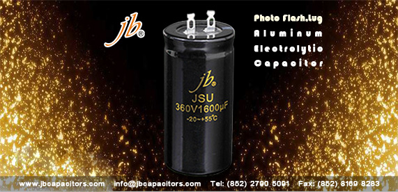
A photoflash capacitor is an electrolytic capacitor used in flash cameras, professional flashes, and also in solid-state laser power supplies. Their usual purpose is to briefly power a high-voltage flash tube, used to illuminate a photographic subject or optically pump a laser rod. As flash tubes require very high current for a very short time to operate, photoflash capacitors are designed to supply high discharge current pulses without excessive internal heating.
Photoflash Aluminum Electrolytic Capacitors are very special capacitors and need very high quality and professional technology. I have friends told me that jb Capacitors Company produce very good quality photoflash electrolytic capacitors. JSU Series--Photo-Flash-Lug-Aluminum-Electrolytic-Capacitors. Here is the datasheet link:http://www.jbcapacitors.com/Aluminum-Electrolytic-Capacitors/JSU-Photo-Flash-Lug-Aluminum-Electrolytic-Capacitor.html
2011-8-5 15:3:2
views
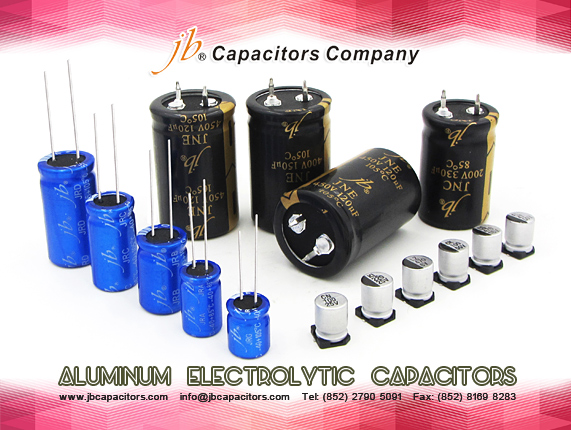
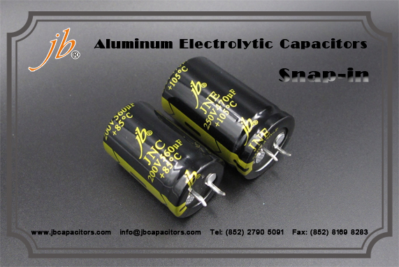
jb capacitors company is very strong on Aluminum electrolytic capacitors, including snap-in, screw type and lug type.
Snap-in Aluminum Electrolytic Capacitors is widely used on power supply. If the end product is industrial motor, some customer may requires to add a mica sheet of plastic layer or other non-flammable material between the Aluminum electrolytic body and PCB. As we know, the motor has vibrations, and it keeps running 24 hours, so that the capacitor will be very hot. The piece of plastic layer is used as insulation to prevent the capacitor from shorting itself.
2011-8-1 15:49:43
views
jb capacitors company not only produce MKT MKP Film capacitors, also produce high quality Screw
terminals Aluminum Electrolytic capacitors, some people called Large can aluminum electrolytic capacitors, I.E. Snap-in, Screw, Lug type. Long load life, high ripple current...
Recently jb strongly recommend screw type aluminum electrolytic capacitors, with very high quality, widely use in power supply, UPS, Welding Machines, filter etc...
See below our strong series:
JMJ--Screw terminal aluminum electrolytic capacitors, 2000hours at 85C'---cross: Epcos B41456,B41458/ B43456,B43458/ B43564, B43584/ B43455, B43457 CDE: CGS series
JML--Screw terminal aluminum electrolytic capacitors, 2000hours at 105C'--Cross:
Epcos B43740,B43760/B41560,B41580/ B43450,B43770(high ripple current)
JMN--Screw terminal aluminum electrolytic capacitors, 5000hours at 85C'
JMQ--Screw terminal aluminum electrolytic capacitors, 5000hours at 105C'