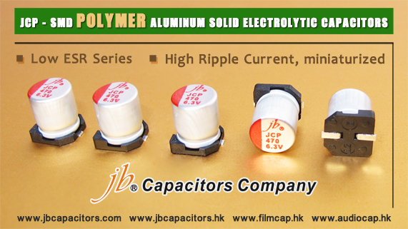
jb Launched JCP Series SMD Conductive Polymer Aluminum Solid Electrolytic Capacitors

JCP Series is another Polymer Aluminum Solid Electrolytic Capacitors with surface mount type. With stable temperature and load life characteristics, JCP series have excellent performance in ripple absorption, smoothing and transient response suitable for numerous applications.

Electrical Characteristics Comparison of Capacitors

Species/Type

High Frequency

Temperature

Allowable Ripple

Miniaturized

Aluminum Electrolytic capacitor

«

«

««

«««

MLCC

«««

«

««

Film Capacitor

«««

«««

«

Tantalum Capacitors

««

««

«

««

JCP(Conductive Polymer Aluminum Electrolytic Capacitors)

«««

«««

«««

««

««« Superior

««Ordinary

«Inferior

jb E3 & E6 Series Values

1.)Capacitors Breakdown voltage

Main article: Breakdown voltage

The breakdown voltage of the dielectric limits the power density of capacitors. For a particular dielectric, the breakdown voltage is proportional to the thickness of the dielectric.

If a manufacturer makes a new capacitor with the same dielectric as some old capacitor, but with half the thickness of the dielectric, the new capacitor has half the breakdown voltage of the old capacitor.

Because the plates are closer together, the manufacturer can put twice the parallel-plate area inside the new capacitor and still fit it in the same volume (capacitor size) as the old capacitor. Since the capacitance of a parallel-plate capacitor is given by: 

this new capacitor has 4 times the capacitance as the old capacitor.

Since the energy stored in a capacitor is given by: 

This new capacitor has the same maximum energy density as the old capacitor.

The energy density depends only on the dielectric. Making a few thick layers of dielectric (which can support a high voltage, but results in a low capacitance), or making many very thin layers of dielectric (which results in a low breakdown voltage, but a higher capacitance) has no effect on the energy density.

2.) Standard values

Before 1960 electronic components values were not standardised. The more common, but not the only, values for capacitors were 1.0, 1.5, 2.0, 3.0, 5.0, 6.0, and 8.0 as base numbers multiplied by some negative or positive power of ten. Values of 0.001 µF and above were stated in microfarads (µF, or often mF); lower values were stated in micro-microfarads (µµF, now called picofarads, pF).

In the late 1960s a standardized set of geometrically increasing preferred values was introduced. According to the number of values per decade, these were called the E3, E6, E12, etc. series

Series

Values

E3

1


2.2


4.7


E6

1


1.5


2.2


3.3


4.7


6.8


E12

1

1.2

1.5

1.8

2.2

2.7

3.3

3.9

4.7

5.6

6.8

8.2

In many applications capacitors need not be specified to tight tolerance (they often need only to exceed a certain value); this is particularly true for electrolytic capacitors, which are often used for filtering and bypassing. Consequently capacitors, particularly electrolytics, often have a tolerance range of ±20% and need to be available only within E6 (or E3) series values.