Half-life of a Capacitor
Symbol:T
Unit:(s)
When a capacitor discharges its charge throught a resistor, the charge of the capacitor decreases with time. The decreasing charge follows an exponential decay curve.
Symbol:T
Unit:(s)
When a capacitor discharges its charge throught a resistor, the charge of the capacitor decreases with time. The decreasing charge follows an exponential decay curve.
A super capacitor is also known as a double-layer capacitor. It polarizes an electrolytic solution to store energy electro statically. Though it is an electrochemical device, no chemical reactions are involved in its energy storage mechanism. This mechanism is highly reversible, and allows the ultra capacitor to be charged and discharged hundreds of thousands of times.
A super capacitor can be viewed as two non reactive porous plates, or collectors, suspended within an electrolyte, with a voltage potential applied across the collectors. In an individual super capacitor cell, the applied potential on the positive electrode attracts the negative ions in the electrolyte, while the potential on the negative electrode attracts the positive ions. A dielectric separator between the two electrodes prevents the charge from moving between the two electrodes.
A super capacitor is also known as a double-layer capacitor. It polarizes an electrolytic solution to store energy electro statically. Though it is an electrochemical device, no chemical reactions are involved in its energy storage mechanism. This mechanism is highly reversible, and allows the ultra capacitor to be charged and discharged hundreds of thousands of times.
A super capacitor can be viewed as two non reactive porous plates, or collectors, suspended within an electrolyte, with a voltage potential applied across the collectors. In an individual supercapacitor cell, the applied potential on the positive electrode attracts the negative ions in the electrolyte, while the potential on the negative electrode attracts the positive ions. A dielectric separator between the two electrodes prevents the charge from moving between the two electrodes.
| Diodes | ||
| Component | Circuit Symbol | Function of Component |
| Diode |  | A device which only allows current to flow in one direction. |
| LED Light Emitting Diode |  | A transducer which converts electrical energy to light. |
| Zener Diode |  | A special diode which is used to maintain a fixed voltage across its terminals. |
| Photodiode |  | A light-sensitive diode. |
| Capacitors | ||
| Component | Circuit Symbol | Function of Component |
| Capacitor |  | A capacitor stores electric charge. A capacitor is used with a resistor in a timing circuit. It can also be used as a filter, to block DC signals but pass AC signals. |
| Capacitor, polarised |  | A capacitor stores electric charge. This type must be connected the correct way round. A capacitor is used with a resistor in a timing circuit. It can also be used as a filter, to block DC signals but pass AC signals. |
| VariableCapacitor |  | A variable capacitor is used in a radio tuner. |
| Trimmer Capacitor |  | This type of variable capacitor (a trimmer) is operated with a small screwdriver or similar tool. It is designed to be set when the circuit is made and then left without further adjustment. |
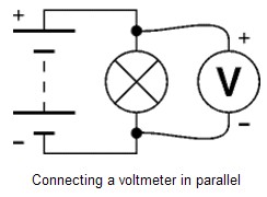
◆Voltage is a measure of the energy carried by the charge. Strictly: voltage is the "energy per unit charge".
◆The proper name for voltage is potential difference or p.d. for short, but this term is rarely used in electronics.
◆Voltage is supplied by the battery (or power supply).
◆Voltage is used up in components, but not in wires.
◆We say voltage across a component.
◆Voltage is measured in volts, V.
◆Voltage is measured with a voltmeter, connected in parallel.
◆The symbol V is used for voltage in equations.
| Lamp(lighting) |  | A transducer which converts electrical energy to light. This symbol is used for a lamp providing illumination, for example a car headlamp or torch bulb. |
| Lamp (indicator) |  | A transducer which converts electrical energy to light. This symbol is used for a lamp which is an indicator, for example a warning light on a car dashboard. |
| Heater |  | A transducer which converts electrical energy to heat. |
| Motor |  | A transducer which converts electrical energy to kinetic energy (motion). |
| Bell |  | A transducer which converts electrical energy to sound. |
| Buzzer |  | A transducer which converts electrical energy to sound. |
| Inductor (Coil, Solenoid) |  | A coil of wire which creates a magnetic field when current passes through it. It may have an iron core inside the coil. It can be used as a transducer converting electrical energy to mechanical energy by pulling on something. |
For more products information please check: http://www.jbcapacitors.com/
It might seem a good idea to make the farad (F) much smaller to avoid having to use µF, nF and pF, but if we did this most of the equations in electronics would have to have factors of 1000000 or more included as well as the quantities. Overall it is much better to have the units with their present sizes which are defined logically from the equations.
In fact if you use an equation frequently you can use special sets of prefixed units which are more convenient...
For example: Ohm's Law, V = I × R
the standard units are volt (V), amp (A) and ohm (Ω),
but you could use volt (V), milliamp (mA) and kilo-ohm (kΩ) if you prefer.
Take care though, you must never mix sets of units: using V, A and kΩ in Ohm's Law would give you wrong values.
The unit (and unit symbol) which is used to measure each quantity. For example: Charge is measured in coulombs and the symbol for a coulomb is C.
Some of the units have a convenient size for electronics, but most are either too large or too small to be used directly so they are used with the prefixes shown in the second table. The prefixes make the unit larger or smaller by the value shown.
Some examples:
25 mA = 25 × 10-3× 0.001 A = 0.025 A
47µF = 47 × 10-6× 0.000 001 F = 0.000 047 F
270kΩ = 270 × 103 Ω= 270 × 1000 Ω= 270 000 Ω F = 47 A = 25
| Prefix | Prefix Symbol | Value | |
|---|---|---|---|
| milli | m | 10-3 | =0.001 |
| micro | µ | 10-6 | =0.000 001 |
| nano | n | 10-9 | =0.000 000 001 |
| pico | p | 10-12 | =0.000 000 000 001 |
| kilo | k | 103 | =1000 |
| mega | M | 106 | =1000 000 |
| giga | G | 109 | =1000 000 000 |
| tera | T | 1012 | =1000 000 000 000 |
The table shows electrical quantities which are used in electronics.
The relationship between quantities can be written using words or symbols (letters), but symbols are normally used because they are much shorter; for example V is used for voltage, I for current and R for resistance:
As a word equation:
voltage = current×resistance
The same equation using symbols: V=I×R
To prevent confusion we normally use the same symbol (letter) for each quantity and these symbols.
Please click on the quantities in the table for further information.
| Quantity | Usual Symbol | Unit | Unit Symbol |
|---|---|---|---|
| Voltage | V | volt | V |
| Current | I | amp* | A |
| Charge | Q | coulomb | C |
| Resistance | R | ohm | Ω |
| Capacitance | C | farad | F |
| Inductance | L | henry | H |
| Reactance | X | ohm | Ω |
| Impedance | Z | ohm | Ω |
| Power | P | watt | W |
| Energy | E | joule | J |
| Time | t | second | s |
| Frequency | f | hertz | Hz |
| * strictly the unit is ampere, but this is almost always shortened to amp. | |||


