2010-12-24 13:27:36
views
Transistors and diodes: These components are often contained in a small plastic package. The connections are made via leads which emanate from the package and are bent so that they touch the board. Three leads are always used for these packages. In this way it is easy to identify which way round the device must go.
2010-12-23 19:15:41
views
Passive SMDs: There is quite a variety of different packages used for passive SMDs. However the majority of passive SMDs are either resistors or capacitors for which the package sizes are reasonably standardized. Other components including coils, crystals and others tend to have more individual requirements and hence their own packages.
Resistor and capacitor packages have a variety of packages. These have designations that include: 1812, 1206, 0805, 0603, 0402, and 0201. The figures refer to the dimensions in hundreds of an inch. In other words the 1206 measures 12 hundreds by 6 hundreds of an inch. The larger sizes such as 1812 and 1206 were some of the first that were used. They are not in widespread use now as much smaller components are generally required. However they may find use in applications where larger powers are needed or where other considerations require the larger size.
The connections to the printed circuit board are made through metallised areas at either end of the package.http://www.jbcapacitors.com/
2010-12-22 19:7:7
views
SMDs, i.e. SMT components, by their nature are very different to the traditional leaded components. They can be split into a number of categories:
- Passive SMDs
- Transistors
- Integrated circuits
2010-12-17 2:29:32
views
Capacitors naturally wear out after extended periods of use. Most capacitors are designed to operate for several thousand hours. Here is the projected lifespan for a typical capacitor, rated for 4,000 hours of operation at an average core temperature of 167 degrees Fahrenheit (75℃).
| Core temperature in degrees F (and ℃) | Projected lifespan in hours of operation |
| 221(105) | 500 |
| 203(95) | 1,000 |
| 185(85) | 2,000 |
| 167(75) | 4,000 |
| 149(65) | 8,000 |
| 131(55) | 16,000 |
| 113(45) | 32,000 |
2010-12-16 15:7:24
views
Capacitors on a motherboard are used to absorb spikes in electrical current and to smooth the flow of power on the motherboard, protecting all of the computer’s components.
Contact our jb, as we are manufacturer of these capacitors and you also contact us if you have technical questions regarding these parts. jb (www.jbcapacitors.com) is a good place to find good capacitors. Our salesman is available to your e-mailed at info@jbcapacitors.com.
2010-12-13 14:38:15
views
Voltage to Current Convertor
When driving the input (base) of a transistor gain stage:
you must convert the input voltage to a current by using a voltage to current convertor --a resistor.
Current to Voltage Convertor
When deriving a voltage from the collector of a transistor amplifier stage:
you convert the output (collector) current into a voltage by using a Current to Voltage convertor in the collector circuit--you guessed it--a resistor.
2010-12-10 12:31:0
views
Polarized fixed capacitor 
A polarized ("polar") capacitor is a type of capacitor that have implicit polarity -- it can only be connected one way in a circuit. The positive lead is shown on the schematic (and often on the capacitor) with a little "+" symbol. The negative lead is generally not shown on the schematic, but may be marked on the capacitor with a bar or "-" symbol. Polarized capacitors are generally electrolytics.
Note that you really need to pay attention to correctly hooking a polarized capacitor up (both with respect to polarity, as well as not pushing a capacitor past its rated voltage). If you "push" a polarized capacitor hard enough, it is possible to begin "electrolyzing" the moist electrolyte. Modern electrolytic capacitors usually have a pressure relief vent to prevent catastrophic failure of the aluminum can (but don't bet your eyesight on this).
2010-12-7 1:5:59
views
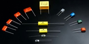
A capacitor is an electronic device for storing charge. Capacitors can be found in almost any complex electronic device. They are second only to resistors in their There are many different types of capacitor but they all work in essentially the same way. A simplified view of a capacitor is a pair of metal plates separated by a gap in which there is an insulating material known as the dielectric. This simplified capacitor is also chosen as the electronic circuit symbol for a capacitor is a pair of parallel plates as shown  .
.
jb Various types of capacitor
2010-12-6 4:20:12
views
Symbol:T
Unit:(s)
When a capacitor discharges its charge throught a resistor, the charge of the capacitor decreases with time. The decreasing charge follows an exponential decay curve.
http://www.jbcapacitors.com/
2010-12-6 1:0:27
views
A super capacitor is also known as a double-layer capacitor. It polarizes an electrolytic solution to store energy electro statically. Though it is an electrochemical device, no chemical reactions are involved in its energy storage mechanism. This mechanism is highly reversible, and allows the ultra capacitor to be charged and discharged hundreds of thousands of times.
A super capacitor can be viewed as two non reactive porous plates, or collectors, suspended within an electrolyte, with a voltage potential applied across the collectors. In an individual super capacitor cell, the applied potential on the positive electrode attracts the negative ions in the electrolyte, while the potential on the negative electrode attracts the positive ions. A dielectric separator between the two electrodes prevents the charge from moving between the two electrodes.
