2011-4-22 16:4:8
views
The typical temperature range for aluminum electrolytic capacitors is –40 °C to 85 °C or 105 °C. Capacitance varies about +5% –40% over the range with the capacitance loss all at cold temperatures. Capacitors rated –55 °C generally only have –10 % to –20 % capacitance loss at –40 °C. Cold temperature performance for rated voltages of 300 V and higher is often worse, and temperature performance varies by manufacturer.
2011-4-20 15:55:3
views
Aluminum Electrolytic Capacitors capacitor element is wound on a winding machine with spindles for one-to-four separator papers, the anode foil, another set of one-to-four separator papers and the cathode foil. These are wound into a cylinder and wrapped with a strip of pressure-sensitive tape to prevent unwinding. The separators prevent the foils from touching and shorting, and the separators later hold the reservoir of electrolyte.
Before or during winding aluminum tabs are attached to the foils for later connection to the capacitor terminals. The best method is by cold-welding of the tabs to the foils with tab locations microprocessor controlled during winding so that the capacitor element’s inductance can be less than 2 nH. The older method of attachment is by staking, a process of punching the tab through the foil and folding down the punched metal. Cold welding reduces short-circuit failures and performs better in high-ripple current and discharge applications in which the individual stakes may fail from high current like buttons popping off one at a time from a fat-man’s vest.
2011-4-19 11:55:32
views
Aluminum Electrolytic Capacitor are connected in series, back-to-back with the positive terminals or the negative terminals connected, the resulting single capacitor is a non-polar capacitor with half the capacitance. The two capacitors rectify the applied voltage and act as if they had been bypassed by diodes. When voltage is applied, the correct-polarity capacitor gets the full voltage. In non-polar aluminum electrolytic capacitors and motor-start aluminum electrolytic capacitors a second anode foil substitutes for the cathode foil to achieve a non-polar capacitor in a single case.
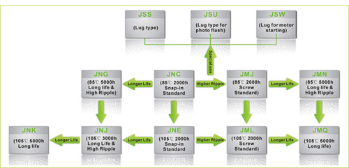
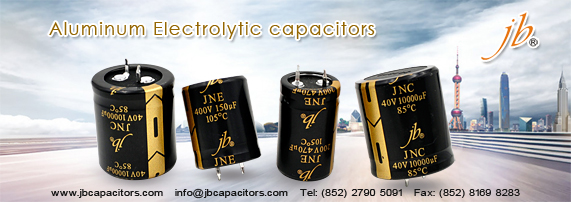
jb Capacitors markets Aluminum Electrolytic Capacitors, including JNC, JNE ,JNG ,JNJ , JNK , JMJ ……The following Picture shows our Aluminum Electrolytic Capacitors. For the detailed information ,We introduced in our website www.jbcapacitors.com .If necessary, you can contact our sales directly. I am sure you can get your satisfaction.
2011-4-6 10:38:58
views
Although Electrolytic Capacitors have much higher levels of capacitance for a given volume than most other capacitor technologies, they can also have a higher level of leakage. This is not a problem for most applications, such as when they are used in power supplies. However under some circumstances they are not suitable. For example they should not be used around the input circuitry of an operational amplifier. Here even a small amount of leakage can cause problems because of the high input impedance levels of the op-amp. It is also worth noting that the levels of leakage are considerably higher in the reverse direction.
2011-4-4 10:36:22
views
Unlike many other types of capacitor, electrolytic capacitors are polarised and must be connected within a circuit so that they only see a voltage across them in a particular way. The capacitors themselves are marked so that polarity can easily be seen. In addition to this it is common for the can of the capacitor to be connected to the negative terminal.
It is absolutely necessary to ensure that any electrolytic capacitors are connected within a circuit with the correct polarity. A reverse bias voltage will cause the centre oxide layer forming the dielectric to be destroyed as a result of electrochemical reduction. If this occurs a short circuit will appear and excessive current can cause the capacitor to become very hot. If this occurs the component may leak the electrolyte, but under some circumstances they can explode. As this is not uncommon, it is very wise to take precautions and ensure the capacitor is fitted correctly, especially in applications where high current capability exists.
2011-4-1 11:45:12
views
The plates of an electrolytic capacitor are constructed from conducting Aluminum foil. As a result they can be made very thin and they are also flexible so that they can be packaged easily at the end of the production process. The two plates, or foils are slightly different. One is coated with an insulating oxide layer, and a paper spacer soaked in electrolyte is placed between them. The foil insulated by the oxide layer is the anode while the liquid electrolyte and the second foil act as cathode.
There are two geometries that are used for the connection leads or tags. One is to use axial leads, one coming from each circular face of the cylinder. The other alternative is to use two radial leads or tags, both of which come from the same face of the cylinder.
The lead styles give rise to the descriptions used for the overall capacitors. Descriptions of axial and radial will be seen in the component references.
2011-3-29 20:16:53
views
Electrolytic capacitance values are not as tightly-specified as with bulk dielectric capacitors. Especially with aluminum electrolytic, it is quite common to see an electrolytic capacitor specified as having a "guaranteed minimum value" and no upper bound on its value. For most purposes (such as power supply filtering and signal coupling), this type of specification is acceptable.
jb Capacitors is a professional manufacturer for aluminum electrolytic capacitors. We have around 30 years manufacturing experience of electrolytic capacitors. Generally speaking, jb Capacitors focuses on large can aluminum electrolytic capacitors and SMD aluminum electrolytic capacitors. All these types of Aluminum Electrolytic Capacitors are detailed introduced in our website: www.jbcapacitors.com.
2011-3-25 12:26:32
views
In aluminum electrolytic capacitors, the layer of insulating aluminum oxide on the surface of the aluminum plate acts as the dielectric, and it is the thinness of this layer that allows for a relatively high capacitance in a small volume. This oxide has a dielectric constant of 10, which is several times higher than most common polymer insulators. This layer can withstand an electric field strength of the order of 25 megavolts per meter which is significant fraction of that of common polymers. This combination of high capacitance and reasonably high voltage result in high energy density.
2011-3-22 17:7:22
views
Aluminum is used for the electrodes by using a thin oxidization membrane.
Large values of capacitance can be obtained in comparison with the size of the capacitor, because the dielectric used is very thin.
The most important characteristic of electrolytic capacitors is that they have polarity. They have a positive and a negative electrode.[Polarised] This means that it is very important which way round they are connected. If the capacitor is subjected to voltage exceeding its working voltage, or if it is connected with incorrect polarity, it may burst. It is extremely dangerous, because it can quite literally explode. Make absolutely no mistakes.
Generally, in the circuit diagram, the positive side is indicated by a "+" (plus) symbol.
2011-3-19 2:20:11
views
In aluminum electrolytic capacitors, the layer of insulating aluminum oxide on the surface of the aluminum plate acts as the dielectric, and it is the thinness of this layer that allows for a relatively high capacitance in a small volume. This oxide has a dielectric constant of 10, which is several times higher than most common polymer insulators. It can withstand an electric field strength of the order of 25 megavolts per meter which is an acceptable fraction of that of common polymers. This combination of high capacitance and reasonably high voltage result in high energy density.
Most electrolytic capacitors are polarized and require one of the electrodes to be positive relative to the other; they may catastrophically fail if voltage is reversed. This is because a reverse-bias voltage above 1 to 1.5 V will destroy the center layer of dielectric material via electrochemical reduction. Following the loss of the dielectric material, the capacitor will short circuit, and with sufficient short circuit current, the electrolyte will rapidly heat up and either leak or cause the capacitor to burst, often in spectacularly dramatic fashion.
