jb Tells You Some Information Regarding Aluminum Electrolytic Capacitors
The electrolytic capacitor has been in use for many years. Its history can be traced back to the very early days or radio around the time when the first broadcasts of entertainment were being made. At the time, valve wireless sets were very expensive, and they had to run from batteries.
However with the development of the indirectly heated valve or vacuum tube it became possible to use AC mains power.
While it was fine for the heaters to run from an AC supply, the anode supply needed to be rectified and smoothed to prevent mains hum appearing on the audio.
In order to be able to use a capacitor that was not too large Julius Lilienfield who was heavily involved in developing wireless sets for domestic use was able to develop the electrolytic capacitor, allowing a component with sufficiently high capacitance but reasonable size to be used in the wireless sets of the day.
Electrolytic capacitor symbols
The electrolytic capacitor is a form of polarised capacitor. The electrolytic circuit symbol indicates the polarity as it is essential to ensure that the capacitor is fitted into the circuit correctly and is not reverse biased.
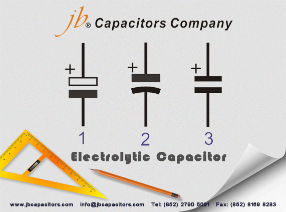
Circuit symbols used for polarised capacitors like the electrolytic capacitor
There is a variety of schematic symbols used for electrolytic capacitors. The first one '1' is the version that tends to be used in European circuit diagrams, while '2' is used in many US schematics, and '3' may be seen on some older schematics. Some schematic diagrams do not print the "+" adjacent to the symbol where it is already obvious which plate is which.


0 Comment so far
Leave a reply