2011-1-18 18:53:4
views
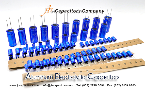
[2] Aluminum Electrolytic Capacitors
The anode in the aluminum electrolytic capacitor is made from a high-purity aluminum foil with an aluminum oxide thin film dielectric on its surface. The capacitor is structured using an electrolytic paper containing an electrolytic solution and an aluminum electrode foil for contacting the cathode.
The thickness of the anode oxide thin film is the distance between the electrodes (t) show at below in the section on how capacitors function. The thickness of the anode oxide thin film in an aluminum electrolytic capacitor is selected by the required withstand voltage. Large amounts of charge can be stored in a small capacitor because the value for t can be made extremely small. This occurs because the value for the electrode surface area (S) can be increased by roughening the surface, and because the dielectric constant ( ) is large.

2011-1-17 23:56:28
views
[1] How Capacitors Work
Below picture shows the basic concepts of how capacitors function.
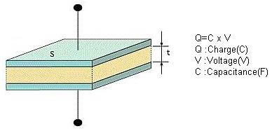
A dielectric material is layered between two metal electrodes, and an electrical charge proportional to the voltage is stored in the capacitor when a voltage is applied across the electrodes.
"C" is the capacitance of the capacitor. The capacitance is calculated using the equation shown below as a function of the surface area of the electrodes (S), the distance between the electrodes (t), and the dielectric constant of the dielectric ( ).
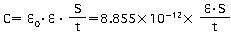
In the formula above, 0 represents the permittivity of free space (8.85 x 10⁻¹²F/m)
A larger capacitance can be obtained by either increasing the dielectric constant, increasing the electrode surface area (S), or by decreasing the distance between the electrodes(t).
The dielectric constant of an aluminum oxide layer averages between 7 and 8. The most frequent dielectric constants of dielectrics used in capacitors are listed in below table.
The effective surface area of aluminum electrolytic capacitors can be increased by as much as 120 times. By roughening the surface of the high-purity aluminum foil, the process makes it possible to produce capacitances far larger than those of other types of capacitors.
| Dielectric Material | Dielectric Constant | Dielectric Material | Dielectric Constant |
| Aluminum oxide thin film | 7 - 8 | Porcelain (ceramic) | 10 - 120 |
| Mylar | 3.2 | Polyethylene | 2.5 |
| Mica | 6 - 8 | Tantalum oxide film | 10 - 20 |
Please note that capacitors are typically described in terms of the primary dielectric material. A few examples are "aluminum electrolytic capacitor" or "tantalum capacitor."
2011-1-14 23:9:19
views
Aluminum electrolytic capacitors are widely used in the circuits of electronic devices. Electrolytic capacitors are attached to printed circuit boards, either individually or in batteries. A common type of aluminum electrolytic capacitor comprises a capacitor element formed by winding an anode foil and a cathode foil through a separator, an electrolyte solution for driving impregnating this capacitor element, a metal case accommodating the capacitor element, and an elastic sealing member sealing the metal case.
Follow jb, you can find the favorite Aluminum Electrolytic Capacitors.Below link you can go to view the favorite Aluminum Electrolytic Capacitors in jb website.
http://www.jbcapacitors.com/Aluminum-Electrolytic-Capacitors/
2011-1-13 22:55:25
views
Glass capacitors can find applications in many areas as a result of their performance characteristics. They do tend to be specialist components and are normally fairly costly.
Circuits exposed to temperature extremes: With the tolerance to a wide range of temperatures, both high and low, some circuits that may be exposed to very harsh environmental conditions may choose to use glass capacitors. Not only can they withstand high and low temperatures, but they do not change value at these extremes by a great amount. Accordingly remote sensors may choose to use glass capacitors.
Applications requiring a high Q circuit: Many circuits including oscillators and filters may require high Q components to give the required performance. Filters will be able to attain their required bandwidth, and for oscillators there are a number advantages including improvement of phase noise performance, reduction in drift and reduction of spurious oscillations.
Low microphony requirements: It may be expedient to use glass capacitors in circuits where microphony may be a problem. RF oscillators including those found in phase locked loops and PLL synthesizers may benefit from their use.
High power amplifiers: The high current capability of glass capacitors may enable their use in RF power amplifiers where other forms of capacitor would not be suitable.
High tolerance areas: In many areas such as filters or free running oscillators the high tolerance and precision accompanied by the low temperature coefficient may be required to maintain the tolerances within a precision circuit.
2011-1-12 22:51:29
views
The construction of glass dielectric capacitors is relatively straightforward to understand. The capacitor consists of three basic elements: the glass dielectric, aluminium electrodes and the encapsulation. However the assembly of the glass capacitors is undertaken in a manner that ensures the required performance is obtained.
As the capacitance between two plates is not always sufficient to provide the required level of performance, the majority of capacitors use a multiplayer construction to provide several layers of plates with interspersed dielectric to give the required capacitance.
Although the glass plates are always flat, and tubular forms of construction are not applicable, the glass capacitors are usually available with leads emanating in either a radial or axial form. Essentially the leads either exit the encapsulation at the side or the end.http://www.jbcapacitors.com/
2011-1-11 23:37:24
views
Glass capacitors offer several advantages over types of capacitor. In particular glass capacitors are applicable for very high performance RF applications:
Low temperature coefficient : Glass capacitors have a low temperature coefficient. Figures of just over 100 ppm / C are often obtained for these capacitors.
No hysteresis : Some forms of capacitor exhibit hysteresis in their temperature characteristic. This is not the case for glass capacitors which follow the same temperature / capacitance when the temperature is rising and falling.
Zero ageing rate : Many electronics components change their value with age as chemical reactions take place within the component. Glass capacitors do not exhibit this effect and retain their original value over long periods of time.
No piezo-electric noise : Some capacitors exhibit the piezo-electric effect to a small degree. This can result in effects such as microphony on oscillators. Where this could be a problem, the use of glass capacitors could help solve the problem.
Extremely low loss / High Q : Glass capacitors are very low loss as there is virtually no dielectric loss. This enables very high Q circuits to be built using them. provided the other components (e.g. inductors) are not lossy.
Large RF current capability : Some capacitors are not able to withstand large values of current. This is not the case for glass capacitors which are suitable for use in RF high power amplifiers, etc.
High operating temperature capability : Glass dielectric capacitors are able to operate at very high temperatures. Many are able to operate at temperatures up to about 200C without fear of damage or performance shortfall.
2011-1-10 23:34:4
views
Glass capacitors are used where the ultimate performance is required for RF circuits. Glass dielectric capacitors offer very high levels of performance, although their cost is high when compared to many other forms of capacitor. Typically a glass capacitor will have a relatively low capacitance value. The values of glass capacitors may range between a fraction of a picofarad up to two to here thousand picofarads. As such these capacitors are used mainly in radio frequency circuit design.
While the performance of glass capacitors is exceedingly high, this is also usually reflected in the cost - it can run into many pounds or dollars for each component. As such glass dielectric capacitors are reserved only for the most exacting RF requirements, often on low volume products where cost is not such an issues as it is in high volume products. The supply of glass capacitors is also limited to a small number of manufacturers and suppliers, and the capacitors may not be available ex-stock.
2011-1-8 1:43:56
views
Mass produced electronic circuit boards need to be manufactured in a highly mechanized manner. The traditional leaded electronic components do not lend themselves to this approach. Although some mechanisation was possible, component leads need to be pre-formed, and when they were inserted into boards automatically problems were often encountered as wires did not fit properly slowing production rates considerably.
It was reasoned that the wires that had traditionally been used for connections were not actually needed for printed circuit board construction. Rather than having leads placed through holes, the components could be soldered onto pads on the board instead. This also saved the need to drilling as many holes in boards.
As the components were mounted on the surface of the board, rather than having connections that went through holes in the board, the new technology was called surface mount technology or SMT. The idea for SMT was adopted very quickly because it enabled greater levels of mechanisation to be used, and it considerably saved on manufacturing costs.
2011-1-7 1:40:9
views
Do you current to urgent need SMD electrolytic Capacitors? Find us jb, jb can solve you this problems.
Voltage Range: 4V ~ 100V.DC
Capacitance Range: 0.1 ~ 470μF, Tolerance +/-20% at 120Hz, 20°C
Load life: 1000H at 105°C, 2000H at +85°C
Size (DXL): 4x5.4mm, 5x5.4mm, 6.3x5.4mm, 6.3x7.7mm, 8x6.2mm.
Lead time: 2-3 weeks


 -butyrolactone